Anesthesia | Eklavya Medical
vaccines
medical_services Main Specialty Domain lock Subscription Required

Anesthesia

Clinical anesthesiology, local and general anesthesia delivery systems, monitoring, and perioperative care.

verified Verified Medical Faculty menu_book 337 Q&A Modules
lock Protected Clinical Document • Pulse App • Screenshots Strictly Prohibited
QUESTION 81 person Asked by .
bookmark_add

Describe the normal physiological mechanisms of thermoregulation. Explain why perioperative hypothermia is so common and its consequences for the surgical patient. Outline evidence-based strategies for prevention and treatment of inadvertent perioperative hypothermia.

collections Question Diagrams & Reference Images (1)
Question Reference Diagram
zoom_in View Image
description Clinical Response
⚙ Core Concept
Inadvertent perioperative hypothermia (IPH) — core temperature <36°C during or after surgery — affects approximately 50–70% of surgical patients who do not receive active warming. Its consequences are serious and measurable: increased surgical site infections, coagulopathy, cardiac events, prolonged drug action, and patient discomfort. NICE guideline CG65 provides specific thresholds and interventions for IPH prevention that have dramatically reduced its incidence in compliant centres. (NICE CG65 2008 updated 2016; Frank SM — Johns Hopkins; Kurz A — NEJM 1996; Sessler DI; Rajagopalan S)
A. Normal Thermoregulation2 marks

Hypothalamic thermostat: the preoptic nucleus of the anterior hypothalamus integrates thermal signals from the skin (peripheral warm/cold receptors) and the blood temperature (central core sensing); it maintains core temperature within a narrow range (36.5–37.5°C) by triggering heat gain or loss responses

Heat production mechanisms: shivering (skeletal muscle tremor — increases metabolic heat production 2–5×); non-shivering thermogenesis (brown adipose tissue in neonates and some adults — uncoupled oxidative phosphorylation); piloerection (traps insulating air — minimal in humans)

Heat loss mechanisms: vasodilation (increases skin blood flow → radiation and convection); sweating (evaporative cooling — most powerful heat loss mechanism at high ambient temperatures); radiation (60% of normal heat loss), convection (15%), evaporation (22%), conduction (3%)

Interthreshold range: the range of core temperatures at which no thermoregulatory response is triggered (approximately 0.2°C wide in awake humans); anaesthesia widens this range dramatically (2–4°C under GA and neuraxial anaesthesia) → the body tolerates a much wider temperature fluctuation without triggering a corrective response

B. Why Perioperative Hypothermia is Common2 marks

Redistribution hypothermia (Phase 1 — first hour): the most important mechanism; GA abolishes the vasoconstrictor response that normally maintains a temperature gradient between the warm core (vital organs) and the cooler periphery (arms, legs, skin); vasodilation from anaesthetic agents → peripheral blood vessels dilate → warm core blood redistributes to the cool periphery → core temperature falls rapidly (1–1.5°C in first 30 minutes despite no net heat loss from the body — the heat has moved from core to periphery); this cannot be prevented by any warming measure alone Heat loss to the environment (Phase 2 — hours 1–3): the patient loses heat to the cool operating theatre environment (typically 18–20°C ambient) through radiation from exposed skin, convection from unwarmed gas flows, and conduction from cold fluid infusions and preparation solutions; the rate of heat loss exceeds metabolic heat production under anaesthesia New equilibrium (Phase 3 — after 3 hours): core temperature stabilises at a new (lower) equilibrium when heat loss and production balance

Contributing factors: cold operating theatre (18–20°C vs optimal 21–22°C); unwarmed IV fluids and blood products (stored at 4°C); unwarmed irrigation solutions; large exposed body cavities (abdominal, thoracic); prolonged surgery; regional anaesthesia (vasodilates below the block level); neonates and extremes of age; thin patients with low body fat

C. Consequences of Inadvertent Hypothermia3 marks

Consequence Mechanism Evidence Surgical Site Hypothermia → vasoconstriction of skin/subcutaneous tissue → ↓ O₂ delivery to the Kurz A (NEJM 1996): maintaining normothermia (36.6°C vs Infection wound → ↓ oxidative bacterial killing by neutrophils → ↑ SSI rate; also impairs 34.7°C) reduced SSI rate from 18% to 6% in colorectal (SSI) collagen deposition surgery — a 3× reduction; this landmark trial established warming as a patient safety standard Coagulopathy Each 1°C below 37°C → 10% reduction in coagulation enzyme activity; platelet Frank SM (Anesthesiology 1997): hypothermic patients (34°C) function impaired; fibrinolysis altered; coagulopathy occurs at "normal" PT/APTT required 20% more blood transfusion than normothermic (tested at 37°C in the lab, not at the patient's actual temperature) patients in hip arthroplasty Cardiac Vasoconstriction → ↑ SVR → ↑ cardiac workload; shivering → ↑ O₂ consumption; Frank SM (JAMA 1997): hypothermic patients had significantly events tachycardia → ↑ myocardial O₂ demand; hypothermia → arrhythmias (AF below 35°C, more morbid cardiac events (MI, unstable angina) in the 24 VF below 28°C) hours after major non-cardiac surgery Prolonged Hypothermia reduces hepatic and renal blood flow → ↓ drug metabolism; ↓ plasma NMB duration prolonged by 30–60% at core temperature drug action pseudocholinesterase activity → prolonged succinylcholine; ↓ cytochrome P450 34°C; extends post-operative recovery room time activity; volatile agents: MAC falls ~5% per °C below 37°C → deeper anaesthesia at lower vaporiser settings than expected Patient Post-anaesthetic shivering occurs in 20–60% of patients; increases O₂ consumption Shivering: treat with pethidine 25 mg IV (most effective) or discomfort 400–500%; increases CO₂ production → impairs wound oxygenation; profoundly ondansetron; prevent with active warming and shivering uncomfortable — frequently rated by patients as the worst part of their surgical experience (worse than pain)

D. NICE CG65 Prevention Protocol3 marks
✅ NICE CG65 (2008 updated 2016) — Target: Maintain Core Temperature ≥36.0°C Throughout the Perioperative Period
Phase NICE Intervention Preoperative Measure and document core temperature on admission; if <36°C → warm the patient before transfer to theatre (forced-air warming blanket for at least 30 minutes); ward temperature >21°C; risk assessment for hypothermia (neonates, elderly, thin patients, diabetics with autonomic neuropathy — high-risk groups) Intraoperative Forced-air warming over accessible body areas throughout surgery (the most effective intraoperative warming method — provides approximately 70 W of heat input); warm IV fluids and blood products to 37°C for infusion rates >500 mL/hr (fluid warming devices mandatory); warm irrigation solutions to 38– 40°C; theatre temperature 21–22°C minimum; temperature monitoring every 30 minutes (nasopharyngeal, oesophageal, tympanic, or rectal — depending on the surgery); warming mattress for procedures >30 minutes Postoperative Measure temperature on arrival in recovery and every 15 minutes thereafter; if <36°C → active warming (forced-air warming blanket) until ≥36°C; do NOT discharge from recovery until temperature ≥36°C; ensure the patient is comfortable (treat shivering); warm blankets for all patients regardless of temperature
🎤 Viva Corner
Q. Why does core temperature fall rapidly in the first 30 minutes of anaesthesia even in a warm operating theatre with active forced-air warming applied?
The rapid core temperature fall in the first 30 minutes of anaesthesia — even with external warming — represents the redistribution phase of anaesthetic-induced hypothermia, and it is mechanistically distinct from environmental heat loss. In the awake patient, the sympathetic nervous system maintains active vasoconstriction in the peripheral vasculature (skin and extremities) that creates a large temperature gradient between the warm core (37°C) and the cooler periphery (skin temperature approximately 32–34°C). This gradient keeps the heat concentrated in the core compartment — the large thermal mass of the vital organs — while the smaller thermal mass of the cool peripheral tissues acts as an insulating barrier. The body does NOT actually lose significant heat to the environment during this process — the total heat content of the body remains the same. When anaesthesia is induced (with any general anaesthetic agent): peripheral vasodilation occurs (both from direct drug effects on vascular smooth muscle and from inhibition of the hypothalamic vasoconstriction response); the cold peripheral blood (from the extremities and skin) rushes into the central circulation while the warm core blood redistributes to the now-dilated peripheral vessels; this internal redistribution mixes warm core blood with cool peripheral blood, dropping the measured core temperature by 1–1.5°C in 30–60 minutes. The paradox: this is NOT heat loss from the body to the environment (total body heat content has not changed) — it is redistribution of existing heat from the core to the periphery. This is why external warming during this phase is relatively ineffective — you cannot prevent redistribution from inside the body by warming the outside; and this is why preoperative warming (warming the peripheral compartment before induction so there is less cold blood to redistribute) is more effective than intraoperative-only warming: NICE CG65 recommends at least 30 minutes of preoperative forced-air warming in high-risk patients for exactly this reason.
★ Examiner's Pearl
The three-phase hypothermia model (Phase 1: redistribution — rapid core fall; Phase 2: heat loss to environment; Phase 3: new equilibrium) with the mechanism of Phase 1 (redistribution, not environmental loss — total body heat unchanged) is the physiological insight most specifically tested. Kurz NEJM 1996 (normothermia → 6% SSI vs 18% hypothermic) is the landmark evidence trial. NICE CG65 threshold (core temp ≥36°C throughout; forced-air warming as most effective method; warm fluids for infusion rates >500 mL/hr) are the specific guideline numbers tested.
NICE CG65. Inadvertent perioperative hypothermia 2008 (updated 2016). Kurz A et al. Perioperative normothermia to reduce the incidence of SSI (NEJM 1996;334:1209-1215). Frank SM et al. Perioperative maintenance of normothermia reduces the incidence of morbid cardiac events (JAMA 1997;277:1127-1134). Sessler DI. Temperature monitoring and perioperative thermoregulation (Anesthesiology 2008;109:318-338).
lock Protected Clinical Document • Pulse App • Screenshots Strictly Prohibited
QUESTION 82 person Asked by .
bookmark_add

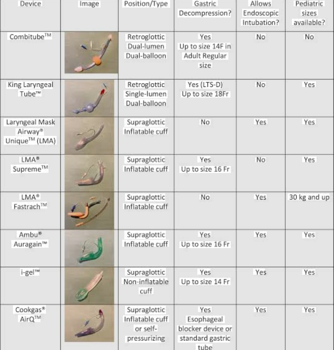
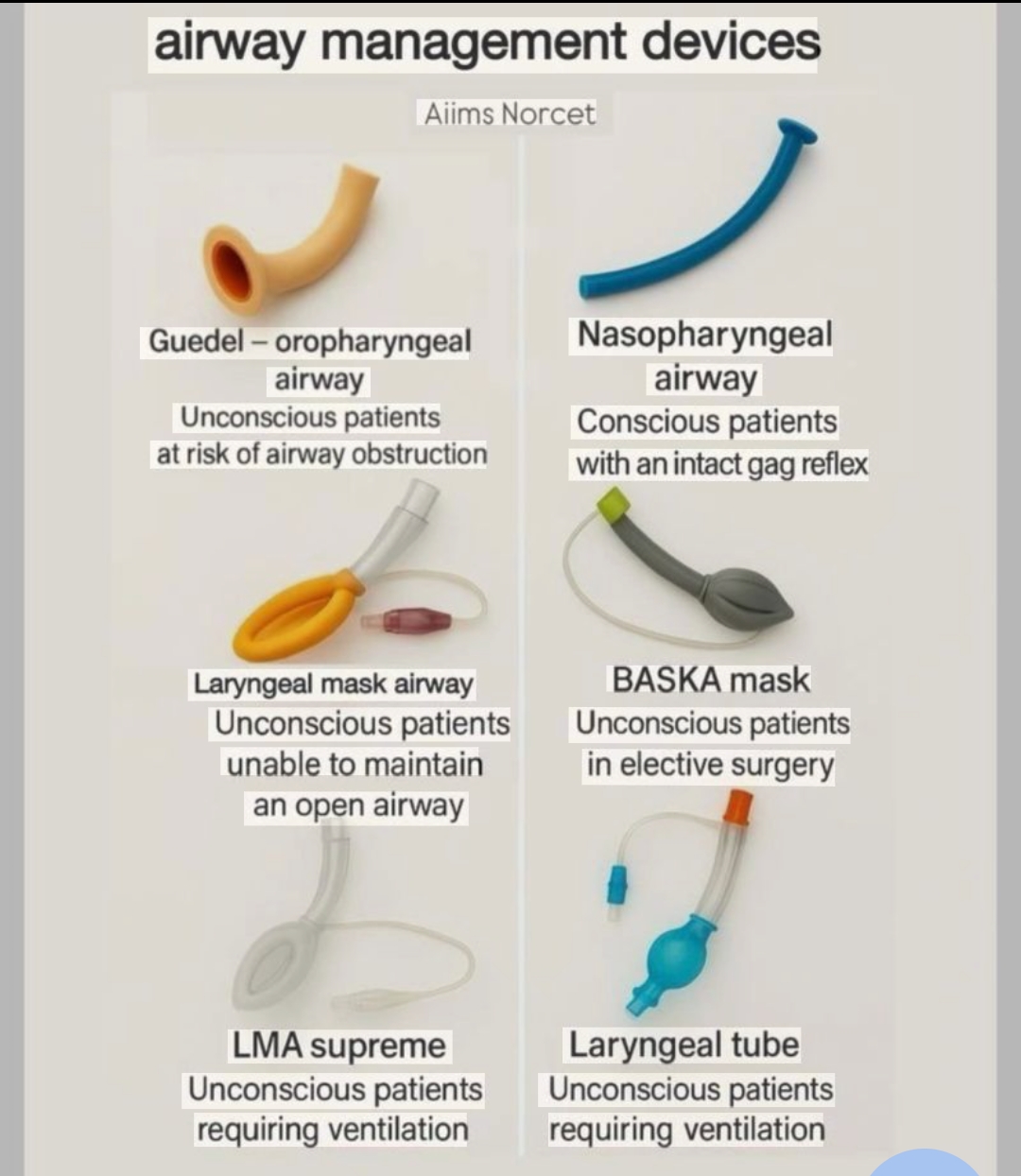
Q85: Classify supraglottic airway devices (SADs). Describe the design features of the i-gel. Compare first-generation vs second-generation SADs. Outline indications, contraindications, and the evidence for i-gel use including as a conduit for fibreoptic intubation and in cardiac arrest.
collections Question Diagrams & Reference Images (1)
Question Reference Diagram
zoom_in View Image
description Clinical Response
⚙ Core Concept
Supraglottic airways have transformed airway management over the last 35 years — from simple adjuncts for spontaneously breathing patients to complex second-generation devices capable of positive-pressure ventilation during major abdominal surgery, as conduits for fibreoptic intubation in the difficult airway (Plan B in the DAS algorithm), and as rescue devices in CICO emergencies. The i-gel (Intersurgical), with its non-inflatable gel cuff that contours to the perilaryngeal anatomy, represents a major design advance — simpler to insert, generating high seal pressures without cuff inflation, and incorporating a gastric drainage channel. (Brain AI — original LMA; Levitan RM; DAS 2015; ILCOR Cardiac Arrest 2020; Miller's Anaesthesia 9th Ed)
A. Classification of Supraglottic Airways2 marks

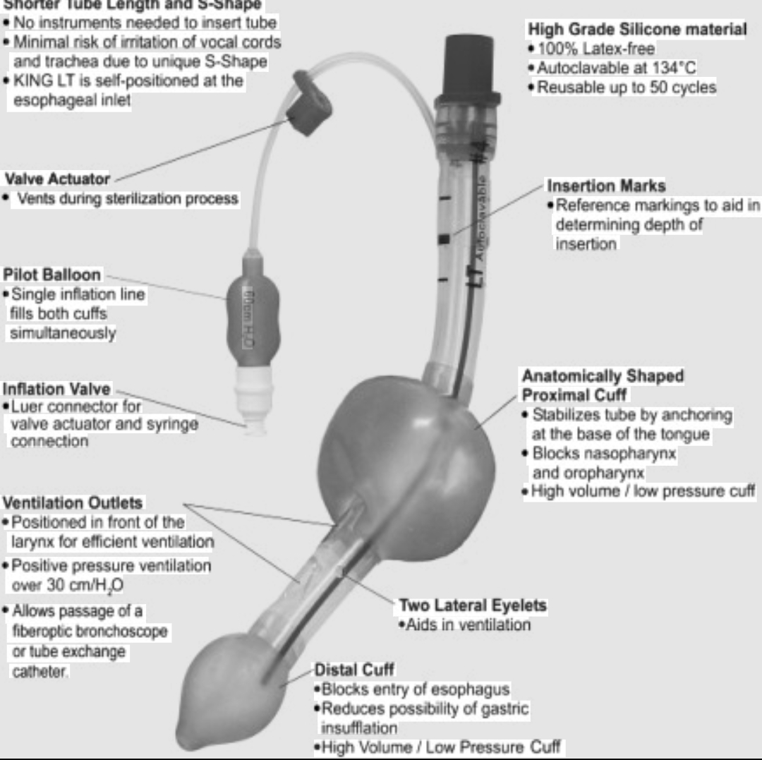
Seal Pressure Generation Features Examples (OLP) First Inflatable cuff; no gastric drainage channel; suitable for spontaneous breathing only or Classic LMA (Brain's original); Portex 15–20 cmH₂O (low generation very low-pressure IPPV; cuff repositions with each inflation; requires inflating balloon to Soft Seal; LMA Unique (single-use) — limits positive (classic) achieve seal pressure ventilation use) Second Higher seal pressures (25–30 cmH₂O); integrated gastric drainage channel (allows NGT i-gel (non-inflatable cuff); LMA 25–35 cmH₂O generation passage and decompresses stomach, reducing aspiration risk); drainage port separates ProSeal (inflatable cuff + gastric (allows positive (advanced) the respiratory and GI tracts; some have bite block and alignment features; suitable for drain); LMA Supreme (single-use + pressure ventilation positive pressure ventilation during surgery gastric drain); LMA Protector; Air-Q for most surgical procedures)

B. i-gel — Design Features2 marks

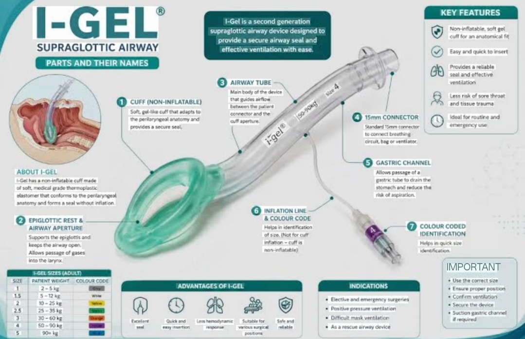
Cuff material: non-inflatable thermoplastic elastomer (TPE) gel — formulated to match the soft consistency of perilaryngeal tissues; the gel cuff moulds to the individual anatomy of the patient's hypopharynx, laryngeal inlet, and perilaryngeal anatomy at body temperature without requiring inflation; eliminates the complications of cuff inflation (cuff over-inflation, cuff herniation, cuff leak)

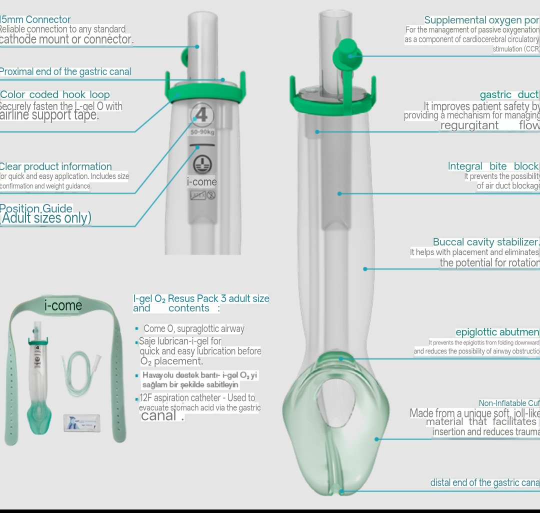
Structure: a short, curved airway tube connecting to a widened cuff that sits in the hypopharynx sealing around the laryngeal inlet; an integrated gastric drainage channel runs parallel to the main airway lumen, terminating at the oesophageal inlet (allows NGT insertion for gastric decompression); a bite block at the proximal end prevents jaw closure from occluding the airway

Sizes: 1 (neonates); 1.5 (infants 5–12 kg); 2 (children 10–25 kg); 2.5 (25–35 kg); 3 (small adult 30–60 kg); 4 (adult 50–90 kg); 5 (large adult >90 kg); selected by patient weight

Advantages: rapid insertion (no cuff inflation step); higher OLP (oropharyngeal leak pressure — 24–30 cmH₂O) than first-generation LMAs; integrated gastric drain (drainage of regurgitated gastric contents via the second channel reduces (but does NOT eliminate) aspiration risk); single-use (infection control); suitable for fibreoptic intubation conduit; suitable as second line (Plan B) in DAS failed intubation algorithm

C. Indications and Contraindications2 marks

Indications Contraindications Elective surgery under GA where ETT is not mandatory (most ENT, orthopaedic, Full stomach / aspiration risk (RSI with ETT preferred); predicted difficult SAD superficial surgery, gynaecological laparoscopy in non-obese); IPPV during placement (limited mouth opening <2.5 cm; fixed neck with pharyngeal surgery (2nd generation SADs can withstand 25–30 cmH₂O to allow controlled pathology; severe pharyngeal/laryngeal pathology); morbid obesity for ventilation); ambulatory anaesthesia (faster emergence, less PONV than ETT); prolonged procedures; high airway resistance/low pulmonary compliance rescue airway in failed intubation (DAS Plan B); cardiac arrest — all ILCOR requiring peak pressures >30 cmH₂O; surgery requiring full neuromuscular guidelines accept SADs as alternative to ETT in cardiac arrest (AHA 2020); bridge blockade with high airway pressures (thoracic, steep Trendelenburg in obese to fibreoptic intubation (Aintree Intubation Catheter through i-gel) patients); head-and-neck surgery where access to the SAD is lost during the case

D. i-gel as Fibreoptic Intubation Conduit2 marks

The i-gel, once placed and ventilation confirmed, can be used as a conduit for fibreoptic-guided intubation (DAS Plan B — after failed intubation, maintain oxygenation with SAD then attempt intubation through it): pass a lubricated fibrescope through the i-gel airway tube → visualise the vocal cords through the SAD aperture → advance a tracheal tube over the fibrescope → confirm intubation with ETCO₂; then remove the i-gel over the ETT

Aintree Intubating Catheter (AIC) technique: a 56 cm catheter (4.7 mm OD) is passed through the fibrescope into the trachea; fibrescope is removed; then a 7.0–8.0 mm ETT is railroaded over the AIC through the i-gel into the trachea; the AIC is then removed; this technique allows intubation through an i-gel with a standard-sized adult ETT

Success rate: approximately 96% intubation success through second-generation SADs in multiple studies; specific i-gel success rate 93–97% for intubation via FOI conduit

Cardiac arrest: ILCOR 2020 and AHA 2020: "SADs are an acceptable alternative to tracheal intubation for airway management during cardiac arrest"; a SAD by a practitioner with limited ETT skill provides equivalent outcomes to ETT in multiple randomised trials; i-gel specifically: AIRWAYS-2 trial (Benger JR, JAMA 2018; n=9,296 out-of-hospital cardiac arrest patients): i-gel vs ETT for cardiac arrest airway management — no difference in neurologically intact survival (primary outcome); i-gel had faster insertion and fewer complications

E. i-gel Insertion Technique2 marks

Select size by weight; lubricate cuff with water-based lubricant (NOT silicone — degrades TPE gel); head in neutral or slightly extended position; open mouth; grasp i-gel with thumb on the bite block; introduce into the mouth aiming the cuff toward the hard palate; rotate and guide the device posteriorly along the hard palate then downward into the pharynx in a single smooth movement until resistance is felt (cuff seated against laryngeal inlet); confirm ventilation (ETCO₂ waveform, bilateral chest movement, absence of epigastric sounds); if poor seal → reinsert or change size
🎤 Viva Corner
Q. After three failed ETT intubation attempts in an obese patient undergoing laparoscopic surgery, you insert an i-gel (size 4) and achieve good ventilation. SpO₂ recovers to 97%. The surgeon insists the operation must proceed. Can you use the i-gel for IPPV during laparoscopy in an obese patient?
The answer is: possibly for a brief period, but it requires careful assessment and I would strongly advocate against proceeding with a high-risk laparoscopy in a morbidly obese patient through an i-gel as the only airway. The assessment: the oropharyngeal leak pressure (OLP) of the i-gel size 4 is typically 24–30 cmH₂O. For laparoscopic surgery in an obese patient with pneumoperitoneum and Trendelenburg positioning, peak airway pressures can rise to 30–40 cmH₂O or higher — potentially exceeding the OLP of even a second-generation SAD, causing: gas leaking around the cuff and into the stomach → gastric distension → aspiration risk → further compromise; loss of ventilation control. Before deciding: test the OLP right now — gently squeeze the reservoir bag while watching the airway pressure gauge; note the pressure at which gas leaks (audible from the mouth or detectable on the pressure gauge); if OLP is ≥25–28 cmH₂O → there may be a safety margin for low-level IPPV. My recommended management: do NOT proceed with laparoscopic surgery through the i-gel in this obese patient — the risks of airway compromise, aspiration, and loss of ventilation during a prolonged pneumoperitoneum + Trendelenburg case are unacceptable. Better options: use the i-gel as a conduit for fibreoptic intubation NOW while the patient is stable and SpO₂ is adequate (pass AIC through the fibrescope into the trachea, railroad an 8.0 mm ETT) — this is the ideal moment to achieve definitive airway; or wake the patient up and plan awake FOI or definitive airway management before rescheduling the laparoscopy. The DAS failed intubation algorithm: if the patient can be safely maintained (SpO₂ adequate, ventilation possible through SAD), wake up and manage the airway electively unless surgery is immediately life-saving — which elective laparoscopy is not.
★ Examiner's Pearl
First vs second generation SAD distinction (second generation has gastric drain + higher OLP 25–30 cmH₂O vs 15–20 cmH₂O for first generation) must be reproduced with specific OLP numbers. The non-inflatable TPE gel cuff mechanism of the i-gel (contours to perilaryngeal anatomy without inflation) is the design feature most specifically tested. AIRWAYS-2 trial (i-gel vs ETT in out-of-hospital cardiac arrest — no difference in neurologically intact survival; i-gel faster insertion) is the landmark evidence for SAD use in cardiac arrest.
Brain AI. The laryngeal mask — a new concept in airway management (BJA 1983;55:801-805). Benger JR et al. Effect of a supraglottic airway device vs ETT during out-of- hospital cardiac arrest on functional outcome — AIRWAYS-2 trial (JAMA 2018;320:779-791). DAS Guidelines 2015 (BJA 2015;115:827-848). Intersurgical i-gel instructions for use. AHA 2020 ACLS guidelines (Circulation 2020;142).
lock Protected Clinical Document • Pulse App • Screenshots Strictly Prohibited
QUESTION 83 person Asked by .
bookmark_add

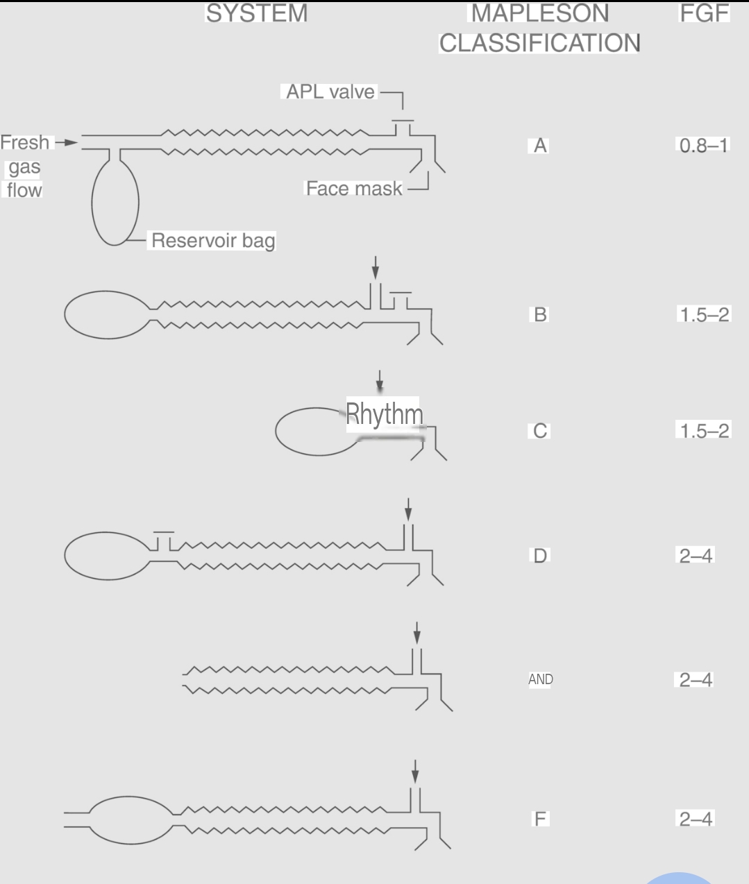
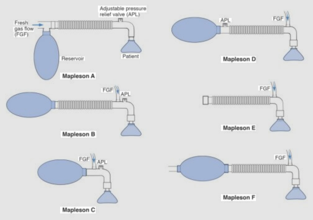
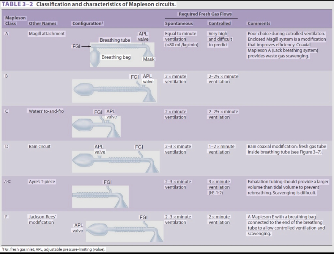
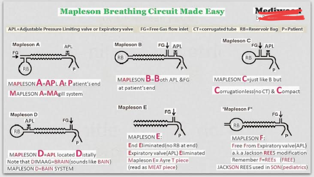
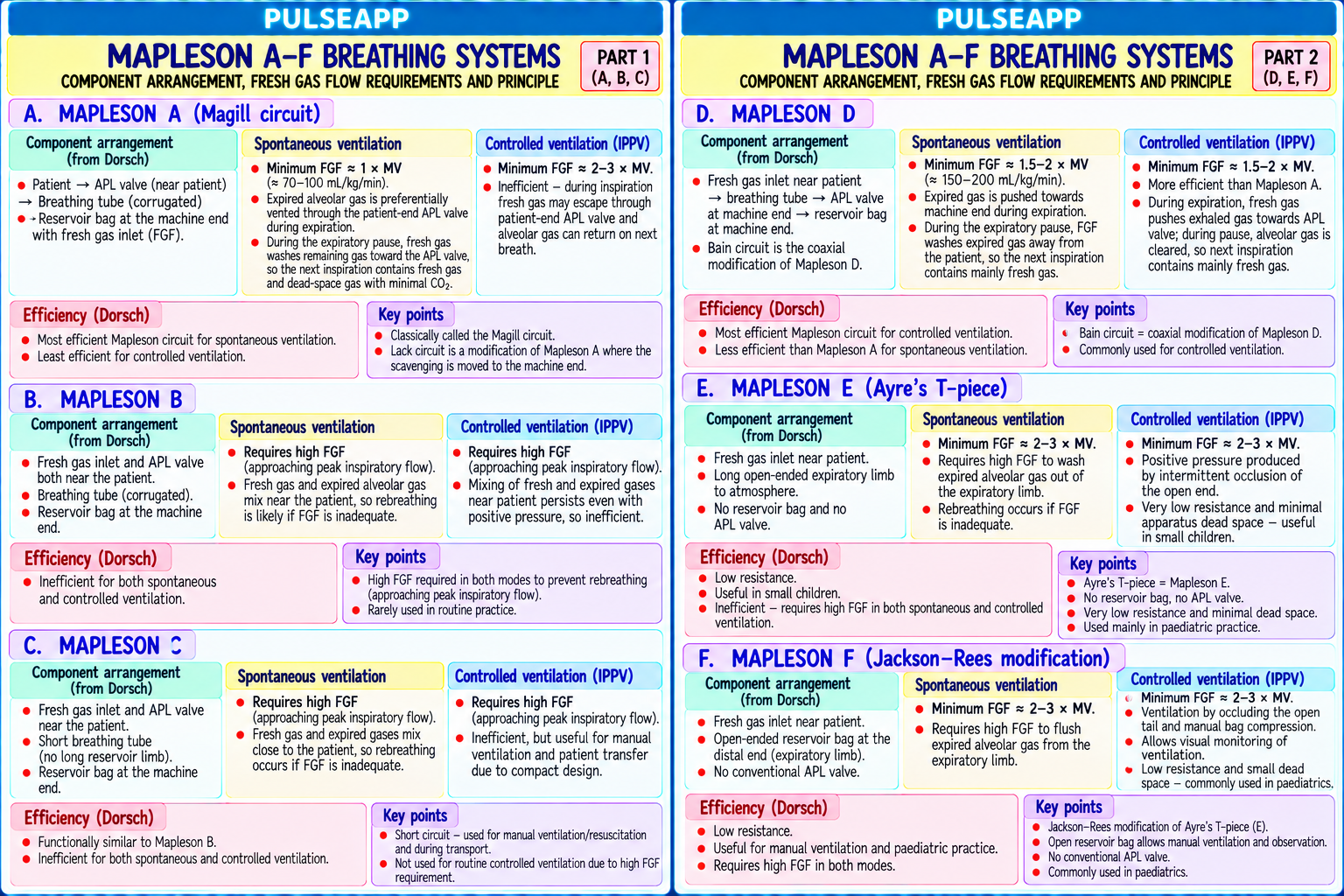
Classify the Mapleson A–F breathing systems. For each: describe the component arrangement, calculate the minimum fresh gas flow for spontaneous breathing and IPPV, and explain why each system has the efficiency it does for each mode of ventilation.

description Clinical Response
⚙ Core Concept
The Mapleson classification (1954) organises non-rebreathing circuits by the relative positions of the FGF inlet, reservoir bag/APL valve, and patient connector. The efficiency of each system in a given ventilatory mode depends on whether CO₂-rich expired gas or fresh gas is preferentially vented through the APL valve at the end of expiration — a principle elegantly captured by understanding the gas flow dynamics specific to each arrangement. (Mapleson WW — BJA 1954; Bain JA, Spoerel WE — 1972; Dorsch JA — Understanding Anaesthesia Equipment; Miller's Anaesthesia 9th Ed)
A. Mapleson Classification Summary4 marks

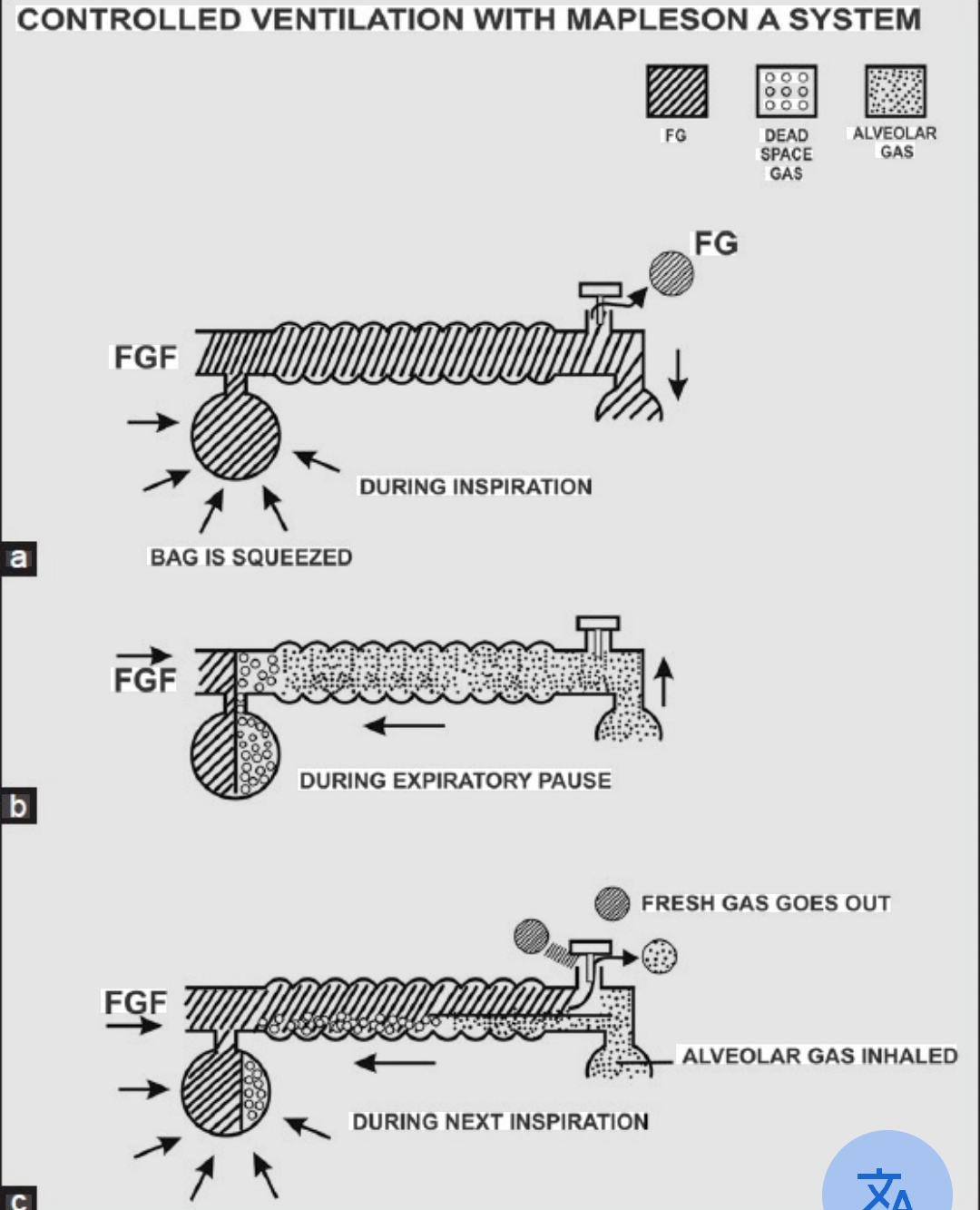
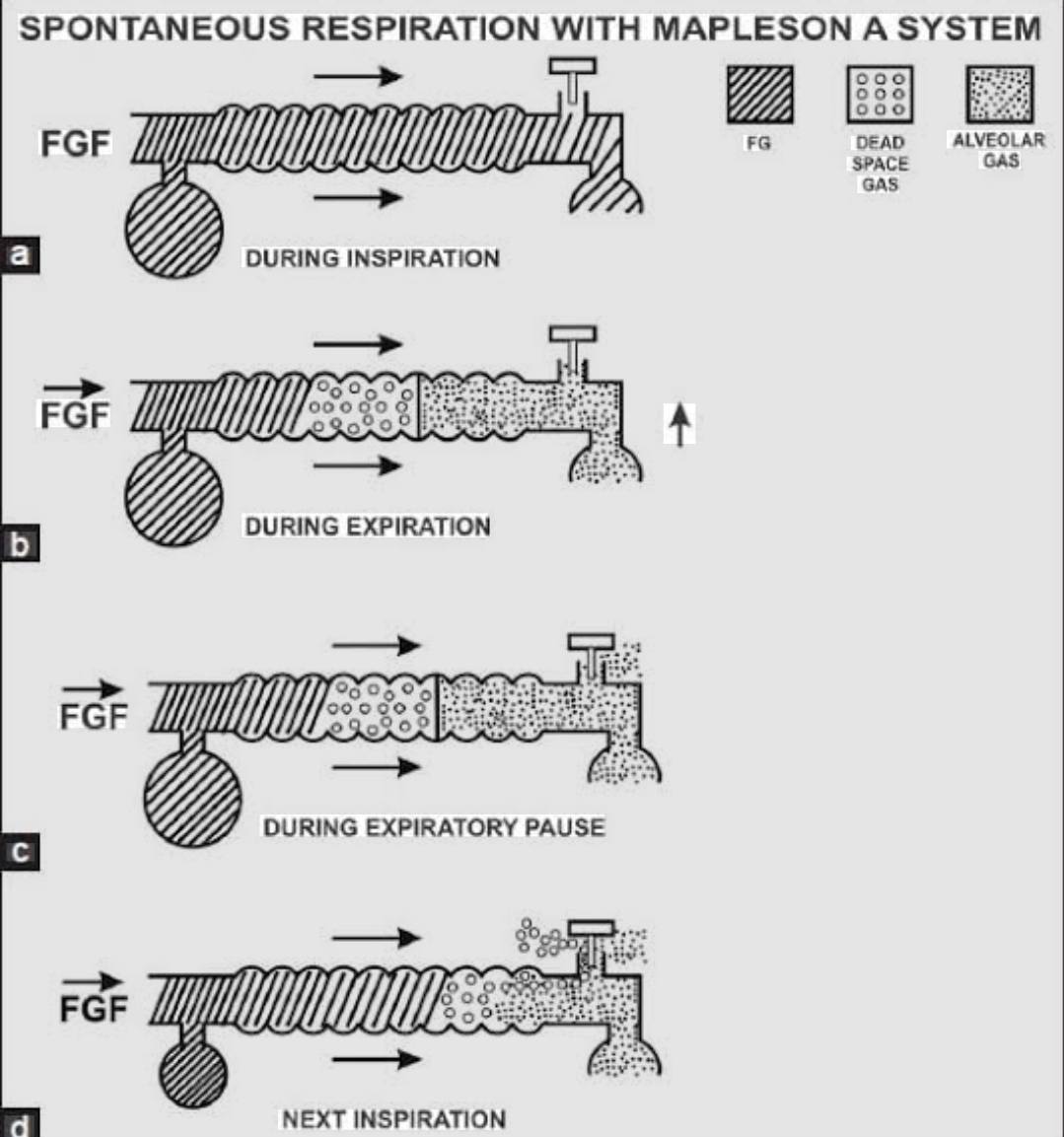
FGF Bag/APL Min FGF Min FGF System Efficiency Explanation Position Position (SB) (IPPV) A (Magill) Near the Near the MV 2–3× MV During SB: expired gas pushes to the patient-end APL → alveolar gas (CO₂-rich) vents first; bag patient (alveolar (10–15 fresh gas fills the space; VERY EFFICIENT for SB (least FGF). For IPPV: PPV pushes (machine (patient ventilation) L/min) mixed gas toward the bag → CO₂-rich gas is not selectively vented; fresh gas wasted — end) end APL) ≈ 4–5 INEFFICIENT for IPPV L/min B Near Near 2–2.5× MV 2–2.5× MV Intermediate efficiency; FGF near patient means fresh gas is available at each inspiration patient patient but expired gas accumulates in the same reservoir C (Waters to- Near Near 2× MV 2× MV Similar to B; CO₂ absorber canister between bag and patient; dead space includes the and-fro) patient patient absorber; largely obsolete in modern practice D (Bain — Near Machine 2–3× MV 70–100 During SB: expired gas may be inhaled from the outer tube before FGF flushes it away — coaxial) patient end (bag) (10–15 mL/kg/min INEFFICIENT for SB (high FGF needed). For IPPV: controlled pattern allows efficient (via inner L/min) (5–7 L/min) flushing of expired gas during expiration → EFFICIENT for IPPV (low FGF sufficient) coaxial tube) E (Ayre's T- Near Open- 2.5–3× MV N/A (no bag No valve or bag; all expired gas vents freely through the expiratory limb; high FGF needed piece) patient ended for IPPV) to prevent rebreathing (must flush entire expiratory limb before next inspiration); simple, (lateral expiratory low-resistance; standard for neonates/infants spontaneously breathing limb) limb (no bag/APL) F (Jackson- Near Open- 2.5–3× MV Available Modification of E with open-ended bag allowing visual monitoring of breathing, manual Rees patient ended bag (manually IPPV, and CPAP; standard paediatric anaesthesia circuit; allows TPEF (total positive modification) on compress the expiratory flow) monitoring expiratory open-ended limb bag)

B. The Efficiency Principle3 marks

Key question: at the end of expiration, just before the next inspiration, which gas is positioned nearest to the patient — fresh gas or CO₂-rich expired alveolar gas?

Mapleson A during SB: FGF enters at the bag end (far from patient); during expiration, the patient exhales → dead space gas first (CO₂-free) → then alveolar gas (CO₂-rich); the alveolar gas pushes toward the patient-end APL valve, which vents it out; the fresh gas from the machine end fills the remaining space; at end-expiration, fresh gas + dead space gas are nearest the patient — essentially no CO₂ near the patient; next breath = minimal rebreathing; only needs FGF ≈ alveolar ventilation (3–5 L/min) to maintain this; MOST EFFICIENT for SB

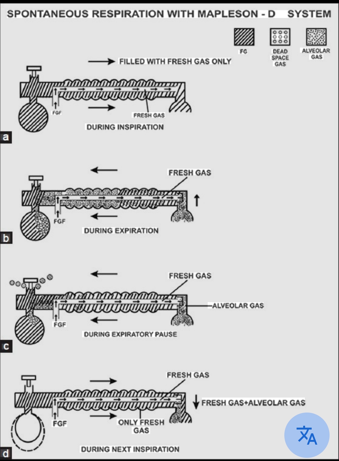
Mapleson D (Bain) during SB: FGF enters at the patient end (via inner tube); expired gas fills the outer tube moving toward the bag; the FGF must flush the entire outer tube of expired gas during expiration before the next breath; if FGF is insufficient, the patient inhales expired gas from the nearest part of the outer tube — rebreathing; needs 2–3× MV to reliably flush; LEAST EFFICIENT for SB

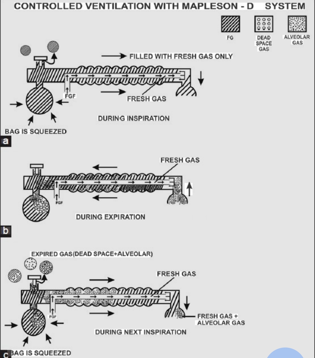
Mapleson D (Bain) during IPPV: controlled pattern of expiration → predictable FGF flushing of the outer tube; lower FGF can maintain normocapnia; 70–100 mL/kg/min sufficient; EFFICIENT for IPPV

C. Bain Circuit — Specific Features (Mapleson D Coaxial)2 marks

Coaxial design: inner tube carries FGF from machine end to patient end; outer corrugated tube carries expired gas from patient toward the machine-end bag/APL; counter-current heat exchange between inspired FGF (cooler) and expired gas (warmer) warms and humidifies inspired gas — an advantage over standard Mapleson D Pethick's test: mandatory pre-use safety check for inner tube integrity; occlude patient end → turn on FGF → reservoir bag should inflate (FGF is being delivered to the patient end, blocked, and fills the circuit); then release → bag should deflate (Venturi effect from FGF venturi draws the bag down); if bag does NOT inflate when occluded → inner tube disconnected (FGF not reaching patient end) → circuit unsafe → DO NOT USE

Applications: head and neck surgery (machine remote from the airway); long cases where inspiratory gas warming is beneficial; controlled ventilation where efficiency is highest; NOT ideal for spontaneous breathing cases (high FGF required)

D. Paediatric Circuit Choice1 mark

Mapleson E (T-piece) for neonates and infants <10–15 kg under spontaneous breathing (low resistance, simple, lightweight) Mapleson F (Jackson-Rees) for manual IPPV and continuous monitoring of breathing in children; the open-ended bag provides visual confirmation of tidal volume and allows CPAP/PEEP application Adult circle system at >25–30 kg (when resistance of circle valves is proportionally less important and CO₂ absorption economics justify the setup)

🎤 Viva Corner
Q. A Mapleson A circuit is set up for a patient breathing spontaneously at a tidal volume of 500 mL and rate of 12/min (MV = 6 L/min). What is the minimum FGF to prevent rebreathing, and how does this compare with a Mapleson D at the same MV?
For a Mapleson A (Magill) circuit during spontaneous breathing: the minimum fresh gas flow to prevent significant CO₂ rebreathing is approximately equal to the patient's ALVEOLAR ventilation — which is MV × (1 − dead space fraction). With a physiological dead space ratio of approximately 0.33 in a normal adult: alveolar ventilation = 6 L/min × 0.67 = 4 L/min. Therefore, a Mapleson A requires approximately 4 L/min FGF to prevent rebreathing during spontaneous breathing at this MV. Some sources simplify this to FGF ≈ MV (6 L/min) as the practical minimum, particularly at higher dead space fractions (anaesthetised patients have increased dead space from factors like V/Q inequality and the breathing circuit dead space). For a Mapleson D (Bain) circuit at the same minute volume (6 L/min): the minimum FGF for spontaneous breathing is 2–3× MV = 12–18 L/min. The Mapleson D requires approximately 2–3 TIMES MORE FGF than the Mapleson A to achieve the same CO₂ rebreathing prevention during spontaneous breathing. The reason: in the Mapleson D, FGF enters near the patient end; expired gas travels toward the bag; without a high FGF, some of this CO₂-rich expired gas in the outer tube may be inhaled at the start of the next breath before FGF can flush it; each litre of expired gas in the tube requires a corresponding high FGF to flush it away within the expiratory time; a 6 L/min MV = 500 mL every 5 seconds = approximately 0.5 L of expired gas in the outer tube that must be flushed before the next inspiration in that 5-second window. The contrast demonstrates clearly why the Mapleson A is the preferred circuit for spontaneous breathing (most economical in gas usage) while the Mapleson D (Bain) is preferred for controlled ventilation (efficient at lower FGF during IPPV).
★ Examiner's Pearl
The full six-system table (A through F) with FGF requirements for both SB and IPPV, especially the crossed efficiency (A = most efficient SB, least IPPV; D = least efficient SB, most efficient IPPV) is the core content. The efficiency principle explanation (which gas is nearest patient at end-expiration?) is the conceptual framework that generates the correct FGF requirements from first principles rather than memorisation. Pethick's test step-by-step (occlude patient end → bag inflates → release → bag deflates; if bag does NOT inflate → inner tube disconnected → unsafe) is a mandatory equipment safety check tested in written papers.
Mapleson WW. The elimination of rebreathing in various semi-closed anaesthetic systems (BJA 1954;26:323-332). Bain JA, Spoerel WE. A streamlined anaesthetic system (Can Anaesth Soc J 1972;19:426). Dorsch JA, Dorsch SE. Understanding Anaesthesia Equipment, 5th Ed. Al-Shaikh B, Stacey S. Essentials of Anaesthetic Equipment, 4th Ed. Miller RD et al. Miller's Anaesthesia, 9th Ed.
lock Protected Clinical Document • Pulse App • Screenshots Strictly Prohibited
QUESTION 84 person Asked by .
bookmark_add

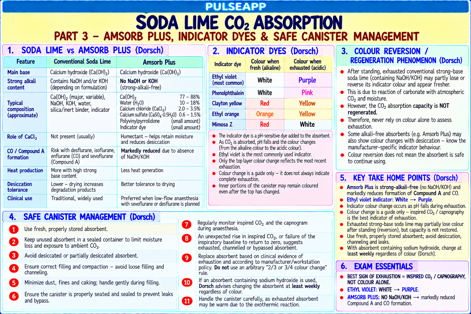
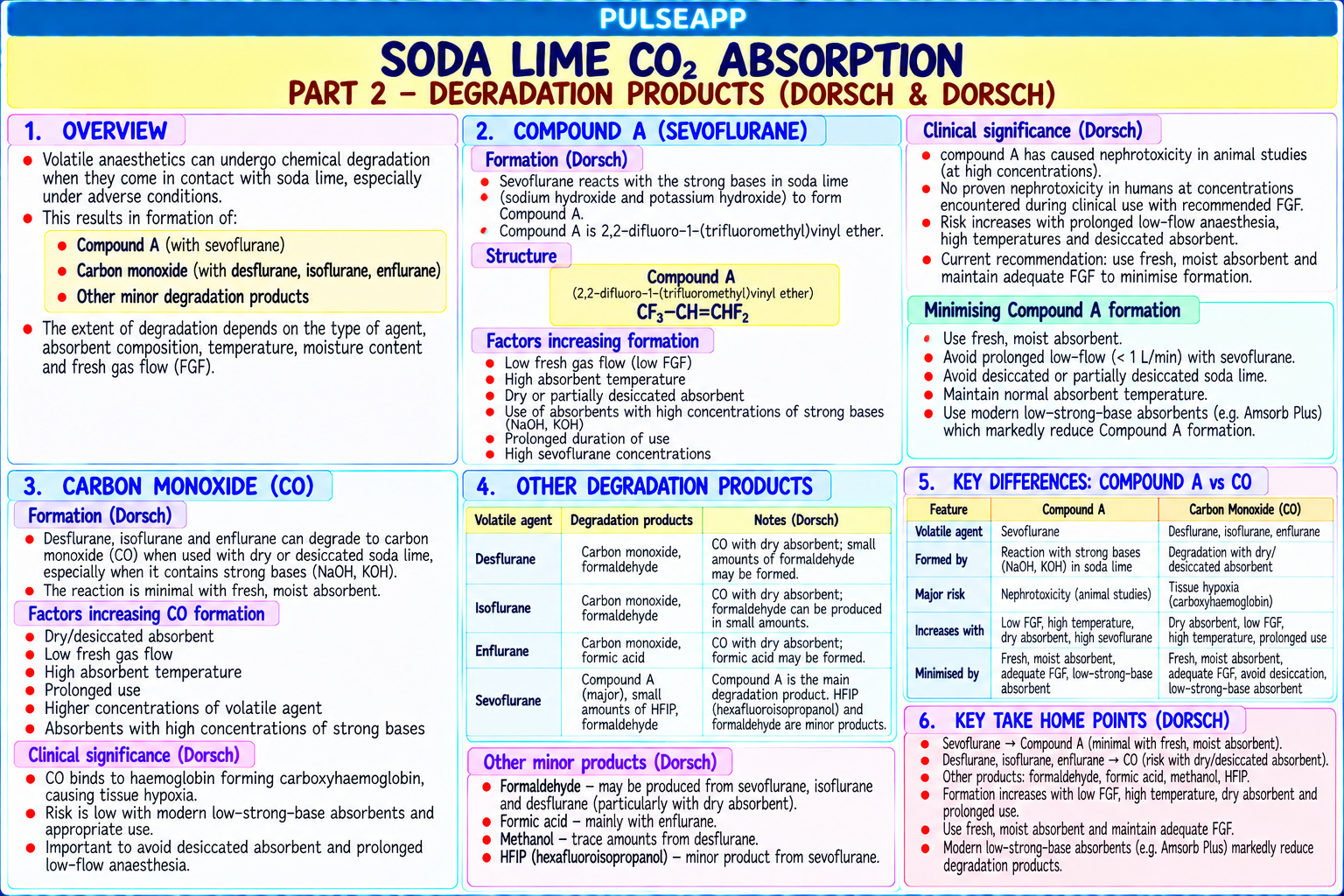
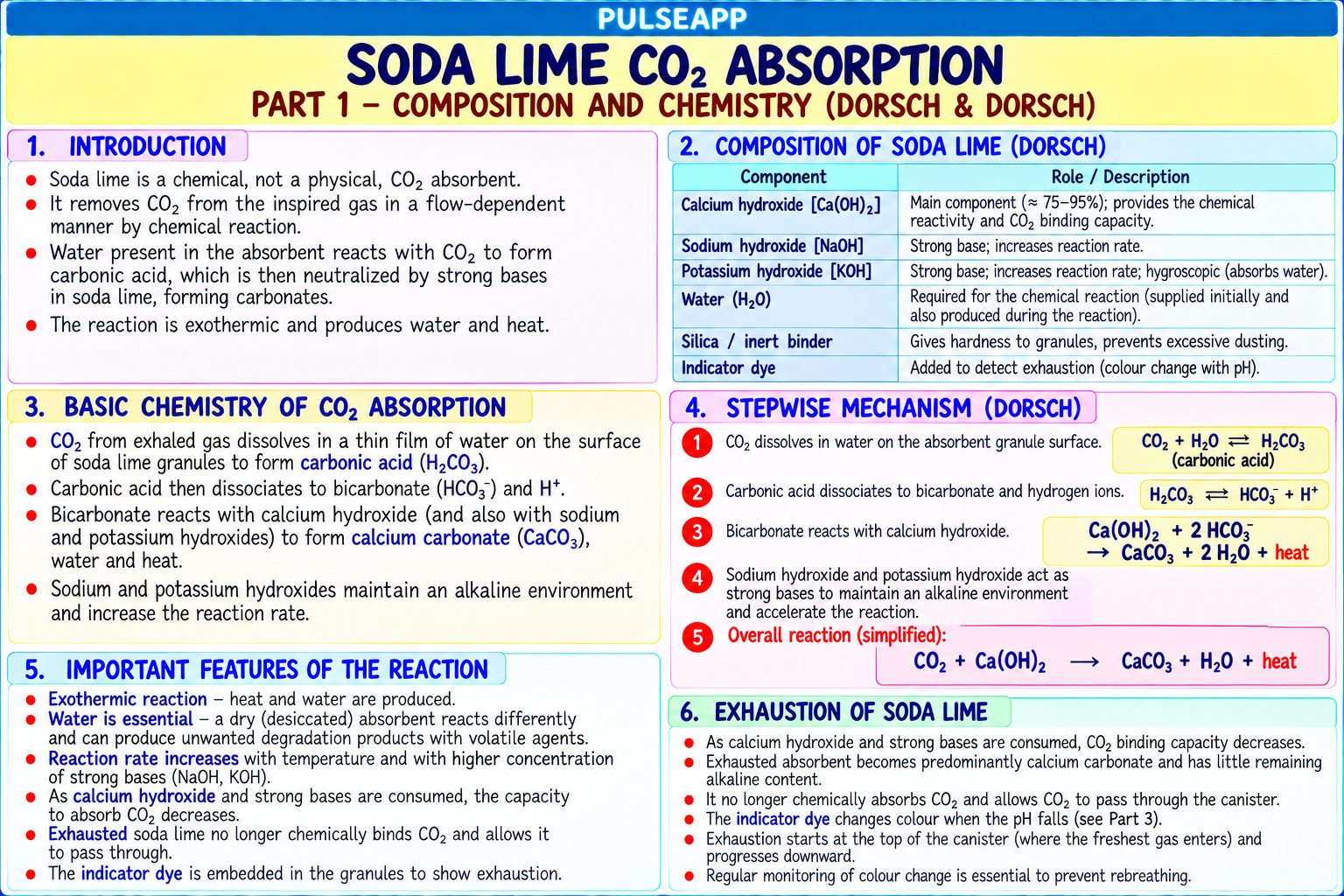
Describe the composition and chemistry of soda lime CO₂ absorption. Explain the formation of Compound A, CO (carbon monoxide), and other degradation products. Compare soda lime with Amsorb Plus. Describe the indicator dye colour changes and safe canister management.

description Clinical Response
⚙ Core Concept
CO₂ absorbents in the circle breathing system neutralise expired CO₂, allowing rebreathing of anaesthetic gases without progressive hypercapnia — making low-flow and metabolic-flow anaesthesia economical and environmentally friendly. However, the strong alkali content of traditional soda lime reacts with certain volatile agents to produce toxic byproducts: Compound A from sevoflurane and carbon monoxide from desflurane, isoflurane, and enflurane — particularly when the absorbent is dessicated. Newer absorbents (Amsorb Plus) eliminate these dangers by removing the strong alkali. (Stabernack CR — Compound A; Wissing H — CO production; Murray JM — Amsorb Plus; Miller's Anaesthesia 9th Ed)
A. Soda Lime Composition and CO₂ Absorption Chemistry2 marks

Standard soda lime composition: Ca(OH)₂ (calcium hydroxide) ~80%; NaOH (sodium hydroxide) ~4%; KOH (potassium hydroxide) ~1%; SiO₂ (silica — hardening agent to reduce dust); water 14–19% (critical — desiccated absorbent is more reactive with volatile agents) Chemical reaction (two-step):

Step 1: CO₂ + H₂O → H₂CO₃ (carbonic acid forms in the water film on granules)

Step 2: H₂CO₃ + 2NaOH → Na₂CO₃ + 2H₂O; and H₂CO₃ + Ca(OH)₂ → CaCO₃ + 2H₂O

Net: CO₂ is neutralised; water and heat are produced (the canister becomes warm — indicates active absorption); Na₂CO₃ and CaCO₃ are the end products (the "spent" absorbent)

Capacity: 1 kg of soda lime absorbs approximately 100–120 L of CO₂ before exhaustion; each breath generates approximately 200 mL of CO₂ → a 1 kg canister lasts approximately 8–10 hours of normal use in a circle system

B. Toxic Byproduct Formation3 marks

Conditions Favoring Byproduct Agent Mechanism Clinical Significance Formation Compound A Sevoflurane High temperature soda Sevoflurane + NaOH/KOH → Nephrotoxic in rats at 150+ ppm (high renal beta-lyase ONLY lime; DESSICATED base-catalysed beta-elimination activity); NOT clinically demonstrated in humans (10– absorbent; high sevoflurane → Compound A (fluoromethyl- 30× lower renal beta-lyase activity); FDA requires concentrations; low FGF 2,2-difluoro-1-[trifluoromethyl]vinyl minimum FGF 1 L/min with sevoflurane in US; Amsorb (less dilution) ether) Plus contains no NaOH/KOH → minimal Compound A generation Carbon Monoxide (CO) Desflurane DESSICATED soda lime Volatile agent haloalkyl groups + Clinically significant CO poisoning reported in patients; >> (critical — water content dessicated NaOH/KOH → CO COHb can reach 30–35% in severe cases; diagnosis Enflurane <5%); highest temperature production via free radical difficult — SpO₂ reads normally (not affected by >> Monday morning case mechanism; desflurane produces COHb); measured with co-oximetry on ABG Isoflurane (absorbent left with dry gas most CO (difluoromethyl ether (NOT flowing all weekend) group most reactive) sevoflurane, NOT halothane) Formaldehyde/Methanol Desflurane Severe dessication Further degradation products Theoretical toxicity; not prominently reported clinically + from desflurane dessicated absorbent

C. Amsorb Plus — The Safer Alternative2 marks

Feature Soda Lime Amsorb Plus Composition Ca(OH)₂ + NaOH/KOH + water Ca(OH)₂ + Ca(OH)₂ (no NaOH or KOH — no strong alkali); CaCl₂ + Ca(SO₄) hardening agents; water

Compound A Yes — NaOH/KOH catalyses Compound A Essentially ZERO — no strong alkali to catalyse beta-elimination; no FDA FGF minimum production from sevoflurane restriction needed with Amsorb Plus

CO production from Yes — dessicated NaOH/KOH reacts with Essentially ZERO — no strong alkali dessication desflurane/isoflurane → CO CO₂ absorption Slightly higher (NaOH/KOH contribute to Slightly lower CO₂ absorption capacity (pure calcium hydroxide less efficient); larger canister capacity absorption capacity) needed for equivalent capacity Cost Lower Higher; but the improved safety profile and elimination of toxic byproducts justifies the premium, particularly for sevoflurane and desflurane

D. Indicator Dyes and Canister Management2 marks

Indicator dyes: ethyl violet (most common) — turns from colourless to VIOLET/PURPLE when the absorbent is exhausted (the rising CO₂ in the spent granules lowers local pH → activates the indicator); alternative: ethyl violet turns purple in acid → spent granules; some formulations use atropine red (red when fresh, colourless when spent)

Important limitation — colour regeneration: ethyl violet can regenerate (return to near-colourless) when the gas flow stops (resting in the dark); a canister that appears fresh may actually be exhausted — colour change cannot be relied upon as the SOLE indicator of absorbent exhaustion; use TIME-based replacement (replace after approximately 8–10 hours of clinical use, or based on ETCO₂ rise as the definitive functional indicator) Canister management: Never allow the absorbent to dessicate (do not leave high-flow dry gas flowing through the circuit when not in use — this is the "Monday morning phenomenon" that produces CO from desflurane)

Replace when: ≥50% of indicator has changed colour; ETCO₂ rises unexpectedly in the circle system; more than 8–10 hours of use Never pack the granules too tightly (prevents channelling of gas flow through the absorbent) Record date of installation; use the oldest canister first from storage

E. Circle System Advantages — Why Low-Flow Anaesthesia Saves Money and the Environment1 mark

The CO₂ absorbent allows the circle system to operate at FGF as low as 0.35 L/min (metabolic flow) — essentially replacing only the O₂ consumed and the agent absorbed by the patient; at metabolic flow, volatile agent consumption falls by 80–90% compared to high-flow techniques; this dramatically reduces both cost (1 mL liquid sevoflurane = approximately £1.00; saving 30 mL per hour = £30/hour) and environmental volatile agent release

🎤 Viva Corner
Q. On a Monday morning, the first patient of the week receives desflurane anaesthesia. Thirty minutes into the case, the SpO₂ is 98%, but the patient appears confused on emergence. How might soda lime be implicated?
This scenario describes the "Monday morning phenomenon" of carbon monoxide production from desflurane with dessicated soda lime — a well-documented perioperative safety hazard. Over the weekend, the anaesthetic machine circle system had high-flow dry gas (O₂ or medical air) passing through the soda lime canister for 48–72 hours (either from a routine safety flow or failure to close the flowmeters) — progressively removing all moisture from the absorbent granules until the water content fell below the critical 5% threshold. When desflurane is used on Monday morning with this completely dessicated, hot soda lime: the difluoromethyl ether group of desflurane reacts with the dessicated NaOH/KOH via a free radical mechanism → CO production; CO levels in the breathing circuit rise; the patient breathes CO → COHb rises; SpO₂ remains 98% (SpO₂ measures O₂Hb vs TOTAL Hb including COHb; in CO poisoning, the SpO₂ reading is falsely elevated relative to true O₂ saturation — the SpO₂ cannot distinguish between OxyHb and COHb); the patient develops CO poisoning symptoms (confusion on emergence, headache, nausea) without a warning from the SpO₂. Confirm: co-oximetry on ABG will show elevated COHb (normal <2%; toxic >10%); treat with 100% O₂ (displaces CO from haemoglobin; CO t½ falls from 5 hours on room air to 60–90 minutes on 100% O₂); severe poisoning → hyperbaric O₂. Prevention: NEVER leave high-flow dry gas running through the soda lime when the circuit is not in use; use Amsorb Plus (no NaOH/KOH → no CO even with dessicated absorbent); consider switching from desflurane (which produces far more CO than sevoflurane, which produces essentially none).
★ Examiner's Pearl
The "Monday morning phenomenon" — dessicated soda lime + desflurane → CO production — is the most clinically significant and specifically tested safety hazard of CO₂ absorbents. Compound A formation (sevoflurane + NaOH/KOH → beta-elimination → Compound A; nephrotoxic in rats but NOT clinically demonstrated in humans) must be stated with BOTH the formation mechanism AND the human safety reassurance. Amsorb Plus contains NO NaOH or KOH — eliminating both Compound A AND CO production — this single fact distinguishes Amsorb Plus from soda lime.
Stabernack CR et al. Sevoflurane degradation by NaOH at clinical concentrations (Anesth Analg 2000;90:410-415). Wissing H et al. CO production from desflurane, enflurane, isoflurane and sevoflurane with dry soda lime (Anesthesiology 2001;95:1205-1212). Murray JM et al. Amsorb — an alternative CO₂ absorbent (Anesthesiology 1999;91:1342-1348). Miller RD et al. Miller's Anaesthesia, 9th Ed.
lock Protected Clinical Document • Pulse App • Screenshots Strictly Prohibited
QUESTION 85 person Asked by .
bookmark_add

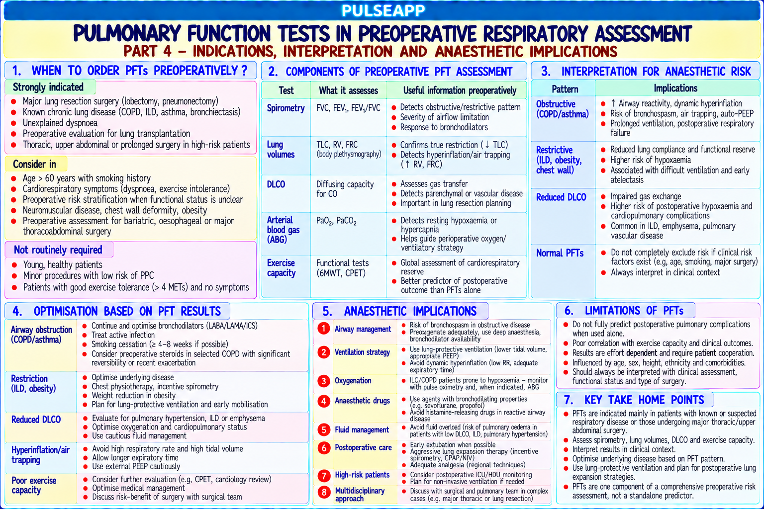
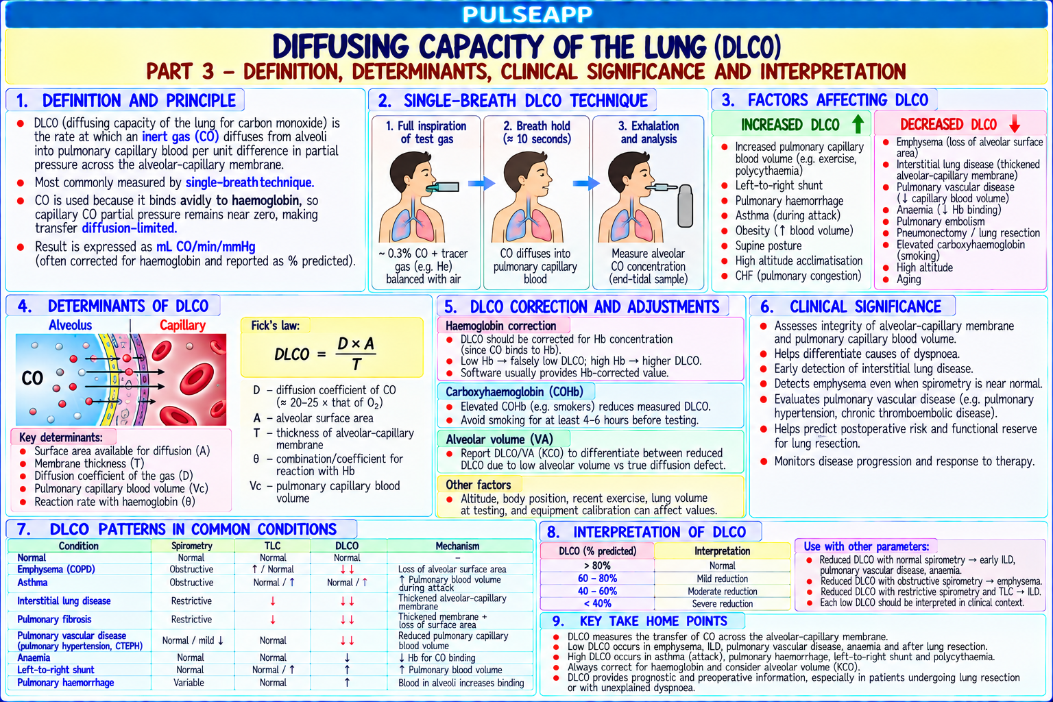
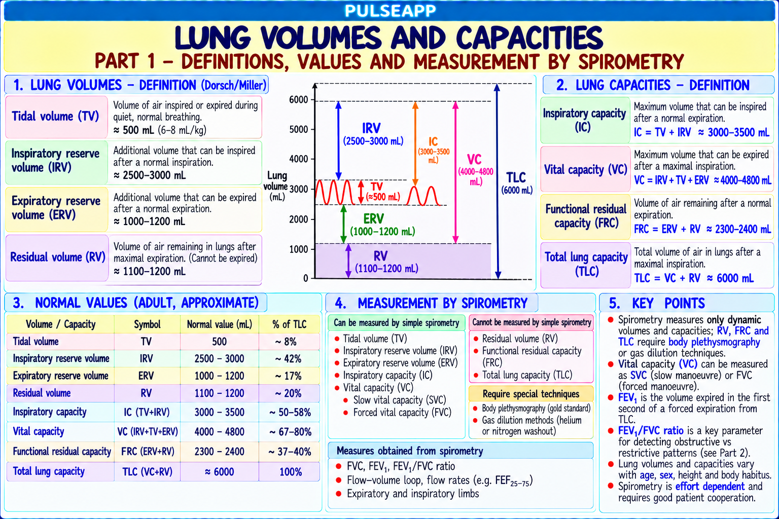
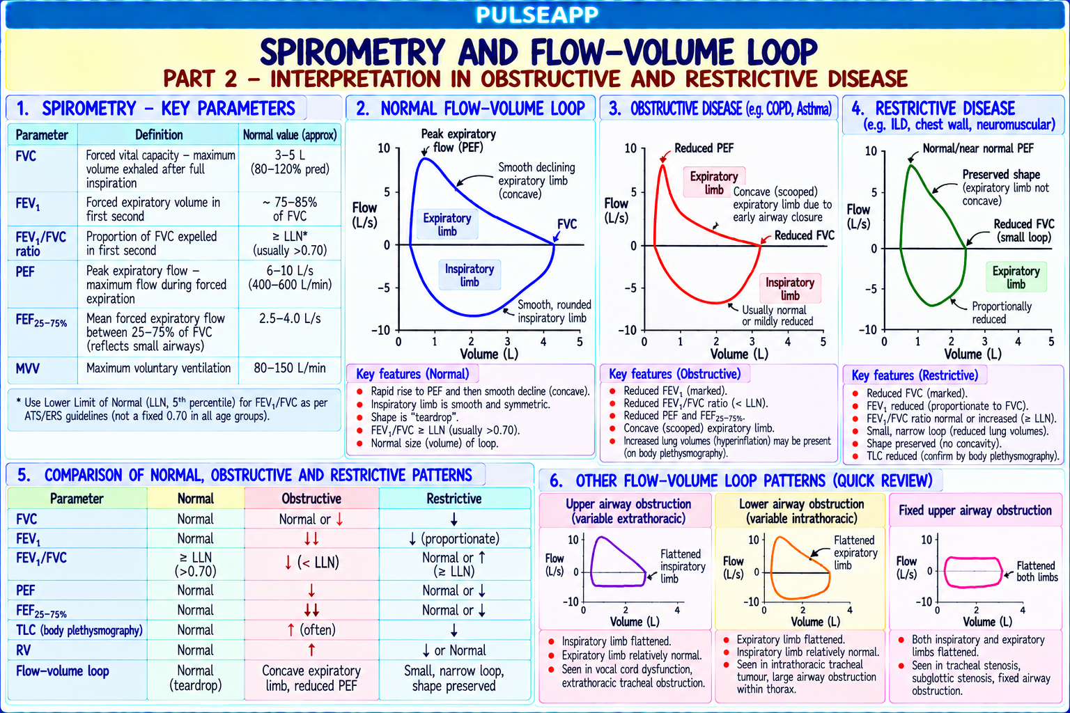
Describe the lung volumes and capacities measurable by spirometry. Explain the flow-volume loop in obstructive and restrictive disease. Define DLCO and its clinical significance. Outline the use of PFTs in preoperative respiratory assessment and the prediction of post-operative complications.

collections Question Diagrams & Reference Images (1)
Question Reference Diagram
zoom_in View Image
description Clinical Response
⚙ Core Concept
Pulmonary function tests provide objective measurement of lung mechanics and gas exchange capacity — the two fundamental determinants of respiratory reserve for surgical patients. Spirometry defines the degree of airflow obstruction (FEV1/FVC ratio) or restriction (all volumes reduced proportionally); DLCO measures alveolar gas exchange efficiency; together they allow the calculation of predicted postoperative (ppo) values that determine operability for lung resection. (Miller's Anaesthesia 9th Ed; Pellegrino R — Interpretation of spirometry; ATS/ERS Standardisation; BTS Guidelines for Lung Resection; Brunelli A)
A. Lung Volumes and Capacities2 marks

Volume/Capacity Definition Normal Value Measured By Tidal Volume (TV) Volume of one normal breath at rest 500 mL (7 Spirometry mL/kg) Inspiratory Reserve Volume Maximum additional volume inhaled after normal ~3000 mL Spirometry (IRV) inspiration Expiratory Reserve Volume Maximum volume exhaled after normal expiration ~1000 mL Spirometry (ERV) Residual Volume (RV) Volume remaining after maximum forced ~1200 mL NOT by spirometry — requires helium dilution, nitrogen expiration — CANNOT be exhaled washout, or body plethysmography Functional Residual Capacity Volume in the lungs at end of normal expiration — ~2200 mL Body plethysmography or gas dilution (NOT spirometry) (FRC = ERV + RV) the "resting lung volume" Total Lung Capacity (TLC = VC Maximum volume in the lungs after maximum ~6000 mL Plethysmography or gas dilution + RV) inspiration Vital Capacity (VC = IRV + TV + Maximum volume exhaled from maximum ~4500 mL Spirometry ERV) inspiration (~70 mL/kg) FEV1 Volume exhaled in the first second of a forced >80% Spirometry (forced) expiration from TLC predicted FEV1/FVC ratio The proportion of VC exhaled in the first second ≥0.70 (70%) Spirometry; FEV1/FVC <0.70 = OBSTRUCTION by ATS/ERS definition

B. Flow-Volume Loops — Obstructive vs Restrictive3 marks

Normal flow-volume loop: inspiration (bottom of loop) is effort-dependent and effort-independent portions; expiration (top of loop) shows a sharp early peak (maximum flow = PEF) followed by a linear decline down to RV; the loop shape depends on lung mechanics Pattern Flow-Volume Loop Appearance Spirometry Clinical Examples Obstructive Scooped/concave expiratory curve (reduced flow at low lung FEV1/FVC <0.70; FEV1 reduced more COPD; asthma (reversibility: ≥12% + 200 mL volumes); expiratory peak flow reduced; loop is wider (↑ RV) than FVC; RV ↑ (air trapping); TLC may FEV1 increase post-bronchodilator); and shorter (↓ VC); the characteristic "shark fin" appearance be ↑ (emphysema) or normal; FVC may emphysema; bronchiectasis with concave expiratory limb be ↓ in severe COPD Restrictive Smaller loop (all volumes reduced proportionally); normal FVC ↓; FEV1 ↓ proportionally; Pulmonary fibrosis; obesity (FRC falls below shape (expiratory limb straight, not scooped); peak flow may FEV1/FVC NORMAL or ↑ (preserved closing capacity); neuromuscular disease be normal relative to lung size; loop is narrower and shorter ratio); TLC <80% predicted (definitive (diaphragm weakness); chest wall deformity but proportionally similar shape to normal criterion for restriction); RV normal or ↓ (kyphoscoliosis); pleural disease Fixed upper Both inspiratory AND expiratory flow plateaus are truncated FEV1/FVC may be normal or mildly Fixed tracheal stenosis; foreign body; airway (flattened) — a "box shape" loop; the fixed obstruction limits abnormal; the specific flattened loop subglottic stenosis; bilateral vocal cord palsy obstruction both inspiratory and expiratory flow equally shape is diagnostic Variable Expiratory flow plateau only (during expiration, positive Characteristic asymmetric flattening of Tracheomalacia; intrathoracic tracheal intrathoracic pleural pressure collapses the obstruction further → worsens expiratory limb tumour obstruction flow limitation); normal inspiratory limb Variable Inspiratory flow plateau only (during inspiration, negative Characteristic asymmetric flattening of Vocal cord dysfunction; large goitre; extrathoracic pleural pressure draws the extrathoracic obstruction inward inspiratory limb extrathoracic tracheal tumour; unilateral obstruction → worsens flow limitation); normal expiratory limb vocal cord palsy

C. DLCO — Diffusing Capacity2 marks

Definition: DLCO (Diffusing capacity for carbon monoxide) measures the ability of the alveolar-capillary membrane to transfer gas from the alveolus to the blood; measured by having the patient inhale a small amount of CO (non-toxic test concentration) and measuring how much is absorbed into the blood over a period; CO is used because it binds haemoglobin with very high affinity (200× O₂) → its uptake is entirely membrane and Hb-limited, not flow-limited

Normal: 25–30 mL/min/mmHg; expressed as % predicted (normal ≥75% predicted) Clinical significance:

Reduced DLCO: emphysema (loss of alveolar-capillary surface area); pulmonary fibrosis (↑ membrane thickness); pulmonary hypertension (↓ blood volume in capillaries); pulmonary haemorrhage (competing CO binding)

Elevated DLCO: polycythaemia (more Hb available for CO binding); pulmonary haemorrhage (blood in alveoli binds CO); left-to-right cardiac shunt (increased pulmonary blood flow) DLCO is the single best preoperative predictor of postoperative pulmonary complications and mortality after lung resection — superior to FEV1 alone; ppoDLCO <40% = very high risk regardless of FEV1

D. Preoperative PFT Assessment for Lung Resection3 marks

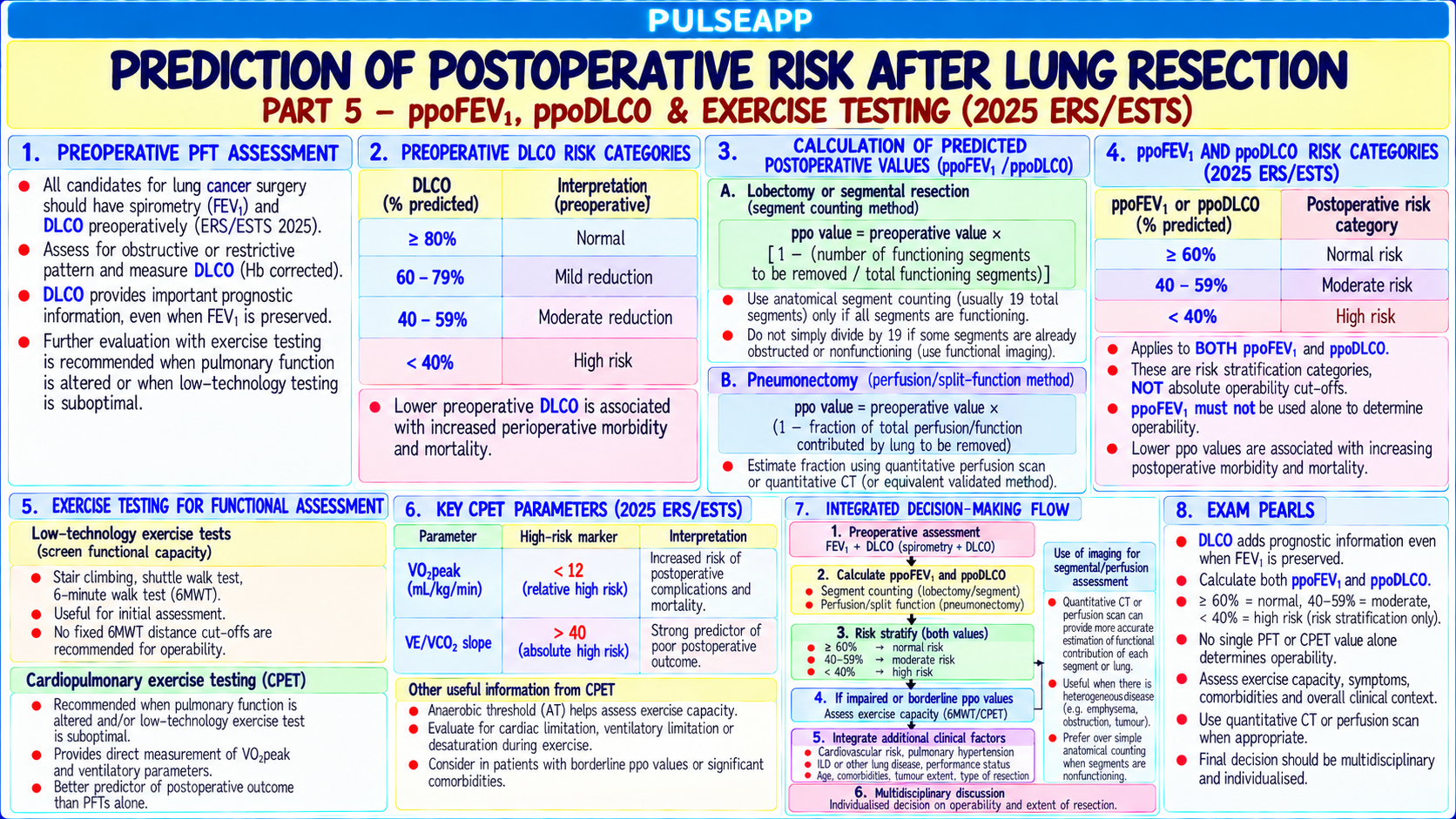
Predicted postoperative values (ppo): both ppoFEV1 and ppoDLCO must be calculated and must both exceed 40% predicted for resection to proceed safely

Formula: ppoFEV1% = preop FEV1% × [1 − (segments resected / total segments)]; total segments = 19 (right lung 10, left lung 9); e.g., right lower lobectomy = 5 segments: ppoFEV1 = FEV1% × (14/19) = FEV1% × 0.74

CPET (Cardiopulmonary Exercise Test): if ppoFEV1 or ppoDLCO <30–40% → CPET for further risk stratification; VO₂max >20 mL/kg/min → low risk; 10–20 → moderate risk; <10 → very high risk (likely inoperable) 6-minute walk test: surrogate for CPET if unavailable; <400 m → high risk; predicts post-resection outcomes

🎤 Viva Corner
Q. A patient with FEV1 65% predicted and DLCO 45% predicted is listed for right pneumonectomy (removing 10 out of 19 segments). Calculate the ppoFEV1 and ppoDLCO. Can you proceed?
Calculating predicted postoperative values for right pneumonectomy (removing the entire right lung = 10 segments out of 19 total): ppoFEV1% = preoperative FEV1% × [1 − (segments removed/total segments)] = 65% × [1 − (10/19)] = 65% × [1 − 0.526] = 65% × 0.474 = 30.8% predicted. ppoDLCO% = preoperative DLCO% × [1 − (10/19)] = 45% × 0.474 = 21.3% predicted. Both values are well below the 40% predicted minimum threshold for safe lung resection: ppoFEV1 30.8% (threshold: ≥40%) — BELOW; ppoDLCO 21.3% (threshold: ≥40%) — BELOW. At this level of predicted postoperative function: the patient would likely require mechanical ventilation post-operatively (cannot sustain adequate spontaneous ventilation with ppoDLCO 21% and ppoFEV1 31%); would almost certainly develop severe exercise limitation, pulmonary hypertension, and cor pulmonale; mortality risk from the procedure itself is very high. My response: this patient is NOT a candidate for right pneumonectomy based on the pulmonary function calculations. I would recommend: refer to CPET to formally quantify exercise capacity (VO₂max); if VO₂max <10 mL/kg/min → the patient is at very high risk and pneumonectomy should not be offered. Multidisciplinary team discussion (thoracic surgeon, oncologist, anaesthesiologist, respiratory medicine) about alternative treatment strategies (stereotactic radiotherapy, endobronchial ablation, or palliation) that might provide oncological benefit without the functionally unacceptable consequences of pneumonectomy in this patient.
★ Examiner's Pearl
The four patterns of flow-volume loop (normal; obstructive — scooped expiratory; restrictive — smaller normal-shaped; fixed upper airway — box shape) with the specific clinical diagnoses must be described and distinguished. The ppo calculation formula (preop% × [1 − segments/19]) with the total segment counts (right 10, left 9, total 19) must be stated correctly — wrong segment counts give wrong answers and lose marks. DLCO as the best single predictor (superior to FEV1 alone) for postresection complications is the key clinical statement.
Brunelli A et al. Physiologic evaluation of the patient with lung cancer being considered for resectional surgery (Chest 2013;143:e166S-e190S). BTS Guidelines on the Selection of Patients with Lung Cancer for Surgery 2010. Pellegrino R et al. Interpretive strategies for lung function tests (Eur Respir J 2005;26:948-968). ATS/ERS Standardisation of Spirometry (Eur Respir J 2005;26:319). Miller RD et al. Miller's Anaesthesia, 9th Ed.
lock Protected Clinical Document • Pulse App • Screenshots Strictly Prohibited
QUESTION 86 person Asked by .
bookmark_add

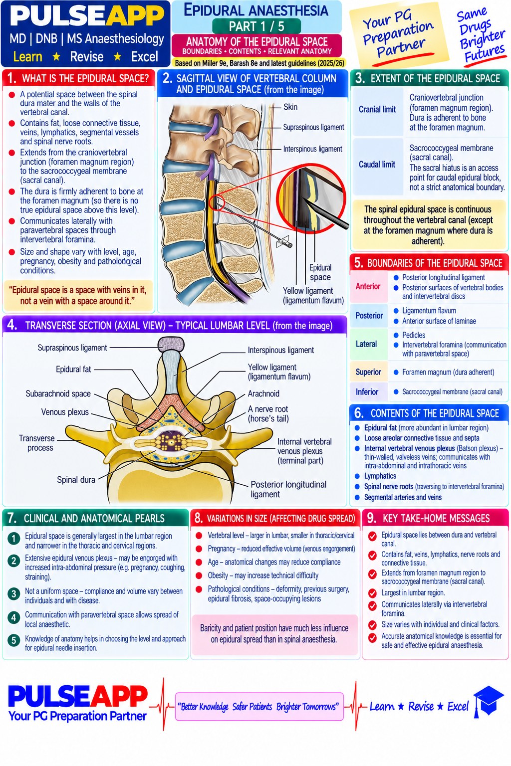
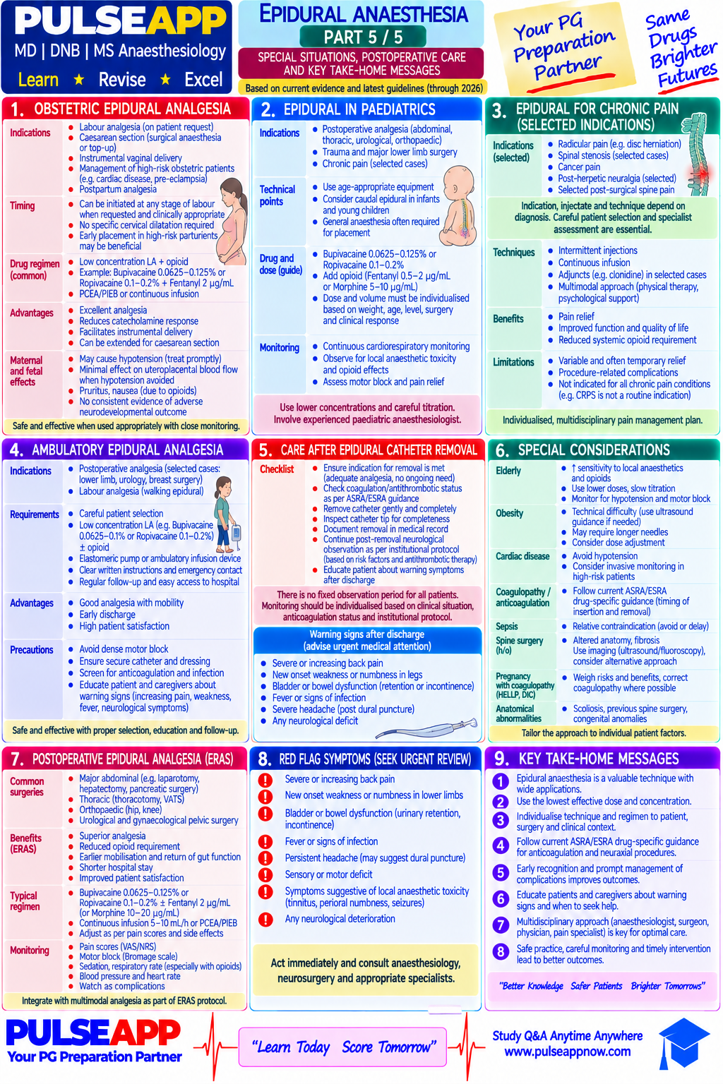
Describe the anatomy of the epidural space in detail — its six boundaries, contents (fat, veins, nerve roots, arteries), pressure characteristics, and the factors determining the spread of drugs injected into the epidural space.

description Clinical Response
⚙ Core Concept
The epidural space anatomy is fundamental to understanding why epidural blocks work, why they fail, and why complications occur. Every clinical feature of epidural anaesthesia — from the "loss of resistance" technique to the volume-dependence of spread, the enhanced spread in pregnancy, the segmental nature of the block — derives directly from the detailed anatomy of this potential space. (Cousins MJ; Hogan QH — cryomicrotome epidural anatomy; Hadzic A; Reina MA — epidural microscopy; Miller's Anaesthesia 9th Ed)
A. Boundaries of the Epidural Space2 marks

Direction Boundary Structure Clinical Notes Superior Fusion of periosteal dura and spinal dura at the foramen Epidural drugs cannot spread intracranially under normal conditions; high blocks can impair (cranial) magnum; the epidural space is a closed cavity cranially cranial nerve function if drug reaches cervical cord (but not intracranial) Inferior Sacrococcygeal membrane (sacral hiatus) — the natural Caudal block: sacral hiatus between sacral cornua; typically 5 mL LA for perineal surgery; 20 (caudal) termination of the spinal canal; accessed for caudal mL for lumbar anaesthesia in adults; 1 mL/kg in children epidural blocks Anterior Posterior longitudinal ligament covering the vertebral The anterior epidural space is narrow at the midline (epidural veins concentrate (ventral) bodies and intervertebral discs anterolaterally); catheter tip may impinge on the posterior longitudinal ligament anteriorly Posterior Ligamentum flavum (flavum = yellow; elastic, dense Loss of resistance technique targets the moment the needle tip exits the ligamentum flavum (dorsal) collagenous ligament connecting adjacent laminae); and into the epidural space; LF is thickest at L3–L4 (5–6 mm) and thinnest at C1 (1–1.5 mm) the posterior surface of the vertebral arch/laminae Lateral Pedicles of the vertebral arches and the intervertebral The lateral spread through intervertebral foramina is partially limited by the dural sleeve (bilateral) foramina; drug spreads laterally through the foramina to around each nerve root; elderly patients have calcified foramina reducing lateral leakage → surround exiting nerve roots more drug confined to the epidural space → wider spread per volume

B. Contents of the Epidural Space2 marks

Epidural fat: the primary content; distributed in lobules throughout the space; acts as a pharmacological depot — lipophilic drugs (opioids, particularly fentanyl and sufentanil) are taken up into epidural fat; acts as a physical spacer determining available volume for drug spread; reduced in elderly (less fat → more drug spreads per unit volume) Batson's venous plexus (epidural veins): an extensive valveless venous network of large, thin-walled veins lying predominantly anterolaterally within the epidural space; drain the spinal cord and vertebral column into the azygous, hemiazygous, and vertebral veins; valveless → blood flows in any direction depending on pressure gradients; during the Valsalva manoeuvre or in pregnancy (IVC compression → elevated epidural venous pressure → engorged veins → reduced epidural space volume → wider spread of same drug volume); veins are a source of significant risk during epidural catheter placement (catheter in vein → intravascular injection of LA → LAST)

Spinal nerve roots and dural sleeves: nerve roots pass laterally from the dural sac to the intervertebral foramina surrounded by dural sleeves (extensions of the dura); these are the primary site of LA uptake and block in epidural anaesthesia; the sleeves provide a surface for drug uptake and spread along the nerve

Radicular arteries: branches of the lumbar and intercostal arteries pass through the intervertebral foramina to supply the spinal cord; vascular injection of LA → immediate LAST; adrenaline in epidural solutions causes vasoconstriction of these vessels (decreasing LA systemic absorption and increasing block duration)

Plica mediana dorsalis: an inconstant fibrous median fold at the back of the epidural space that may divide it partially into two lateral compartments; can cause asymmetric or "one-sided" epidural blocks when a catheter tip is directed into one lateral compartment

C. Pressure Characteristics2 marks

The epidural space is a POTENTIAL space (the dura is normally pressed against the ligamentum flavum by the higher pressure in the subarachnoid space); it contains a small volume of fluid between the dural surface and the surrounding structures

Negative pressure: in most adults (particularly in the thoracic region), the epidural pressure is slightly negative relative to atmospheric pressure; mechanism: the dura is normally apposed to the surrounding structure by cerebrospinal fluid pressure + small negative epidural pressure; the negative pressure was the basis for the historical "hanging drop" technique (a drop of saline in the needle hub would be aspirated into the epidural space when the needle exits the LF) — less reliable than loss of resistance but still used by some clinicians

Pressure variation: epidural pressure rises with Valsalva, coughing, straining, and in pregnancy (engorged veins transmit pressure); abdominal compression during thoracic epidural catheter placement → veins engorge → increased risk of intravascular placement at that moment

D. Factors Determining Drug Spread4 marks

Factor Effect on Spread Magnitude Volume of ↑ Volume → ↑ spread; THE MOST IMPORTANT FACTOR; rule of thumb: 1–1.5 mL per dermatome (segment) for adults Major — predominant injectate determinant Concentration Determines motor vs sensory block intensity but NOT spread; 0.1% bupivacaine → sensory only; 0.5% → motor + Minimal effect on spread Concentration Determines motor vs sensory block intensity but NOT spread; 0.1% bupivacaine → sensory only; 0.5% → motor + Minimal effect on spread sensory Age ↑ Age → ↑ spread per volume; elderly have reduced epidural fat, calcified foramina (less lateral leakage), and reduced Major — reduce dose 30– compliance of the space; same volume spreads ~2× further in a 70-year-old vs a 20-year-old 50% in elderly Pregnancy Engorged epidural veins (from IVC compression) → reduced epidural space volume → same volume spreads further; Major — well established reduce dose 25–30% in pregnant patients clinically Height Taller patients have larger epidural space → slightly less spread per volume; clinical effect modest Minor Weight/Obesity ↑ Intra-abdominal pressure → engorged epidural veins → reduced volume → wider spread; similar to pregnancy effect Moderate Site of Thoracic epidural spreads more cephalad than caudad from the injection point; lumbar epidural spreads more bilaterally Moderate — influences injection choice of insertion level Speed of Faster injection → slightly more turbulence → slightly wider spread; effect modest in clinical practice Minor injection Position of Gravity has modest effects on epidural drug spread (less than in spinal); lateral position → slightly more dependent side Minor for epidural (vs patient block; sitting position → sacral block more reliable major for spinal)

🎤 Viva Corner
Q. What is the plica mediana dorsalis and how does it explain one-sided epidural blocks?
The plica mediana dorsalis (or "dorsal median fold") is an inconstant posterior median fibrous fold within the epidural space that has been observed in anatomical studies — most notably in the detailed cryomicrotome sectional studies of Hogan (1996) who systematically photographed cadaveric epidural anatomy at multiple levels. In some individuals (studies suggest it is present to varying degrees in 50–70% of people), this fold extends from the dorsal surface of the dural sac toward the posterior epidural wall, partially dividing the posterior epidural compartment into two lateral halves in the midline region. In its most complete form, it creates a functional barrier that can direct an epidural catheter tip into one lateral compartment, where the injected drug spreads preferentially on that side and the fold prevents equivalent spread to the other side — producing a unilateral or asymmetric epidural block. This anatomically explains the clinically common phenomenon of the patient with epidural anaesthesia who has a dense block on one side and minimal block on the other despite apparently correct catheter placement and volume of drug. Clinical management: withdraw the catheter 1–2 cm (the catheter tip may have been directed into one lateral compartment and withdrawal may reposition it in the midline); repositioning the patient lateral with the unblocked side dependent allows gravity to assist drug spread to the dependent (unblocked) side; inject an additional 3–5 mL of LA; if still unilateral after these manoeuvres → resit the epidural at a different interspace to avoid the same anatomical fold. The plica also explains why anterior/posterior epidural positions of the catheter tip produce different patterns of spread.
★ Examiner's Pearl
All five boundaries (superior: foramen magnum; inferior: sacrococcygeal membrane; anterior: posterior longitudinal ligament; posterior: ligamentum flavum; lateral: pedicles/intervertebral foramina) with their structure names are specifically tested — not just "the spinal canal." The factors affecting spread ranked by importance (volume first, then age and pregnancy as the major modifiers) must be presented as a table with specific clinical dose adjustments (reduce 25–30% in pregnancy; 30– 50% in elderly). The plica mediana dorsalis and its explanation of one-sided blocks is a targeted anatomical question that differentiates candidates who have read detailed anatomy from those who have only surface knowledge.
Hogan QH. Epidural anatomy examined by cryomicrotome section (Reg Anesth 1996;21:395-406). Cousins MJ, Bridenbaugh PO. Neural Blockade, 4th Ed. Reina MA et al. Ultrastructural anatomy of the epidural space (Anesth Analg 2009). Hadzic A. Hadzic's Textbook of Regional Anesthesia, 2nd Ed. Miller RD et al. Miller's Anaesthesia, 9th Ed.
lock Protected Clinical Document • Pulse App • Screenshots Strictly Prohibited
QUESTION 87 person Asked by .
bookmark_add

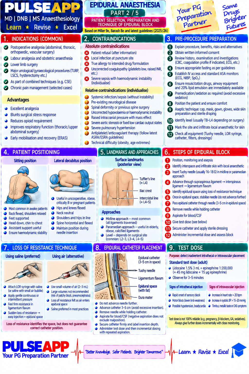
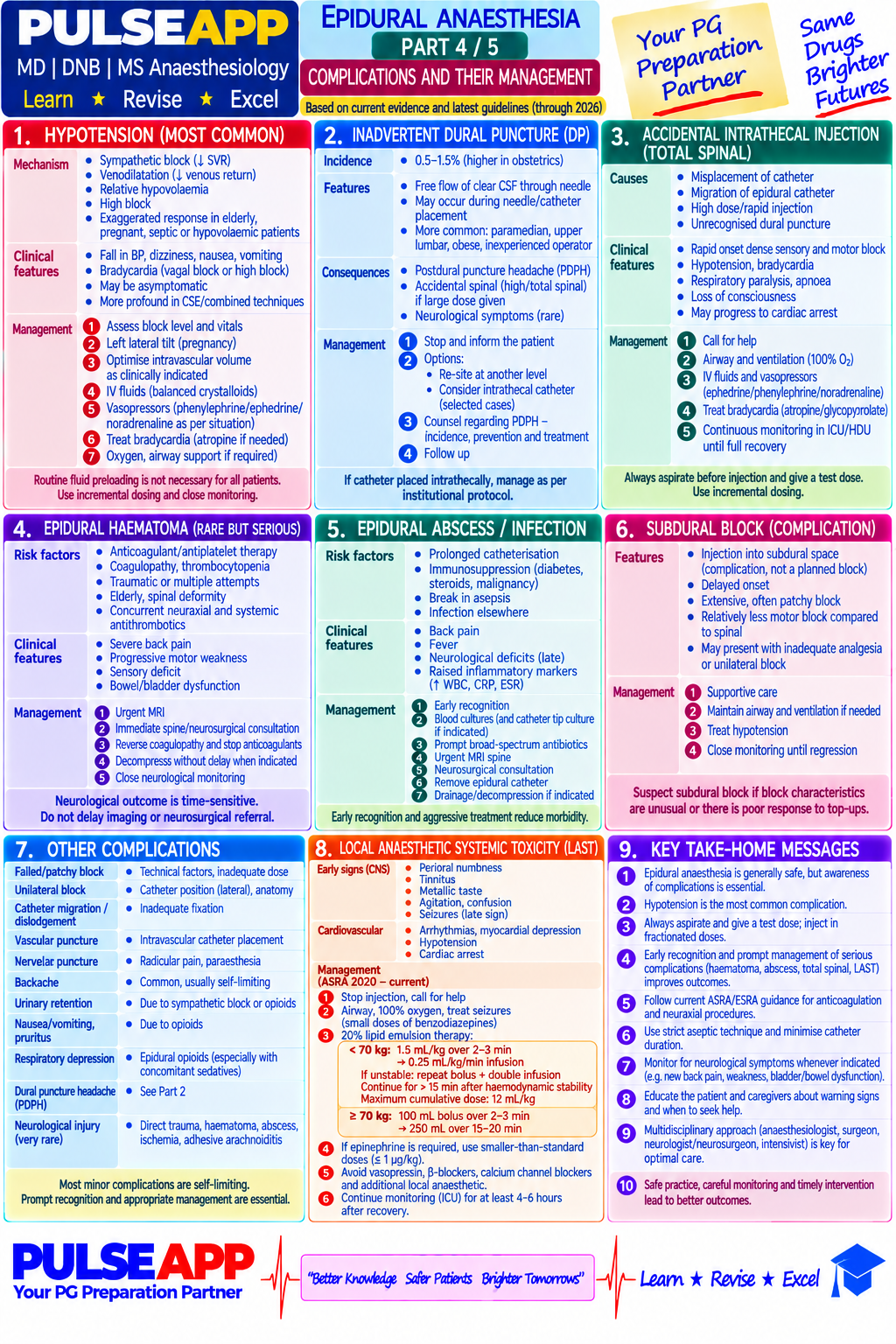
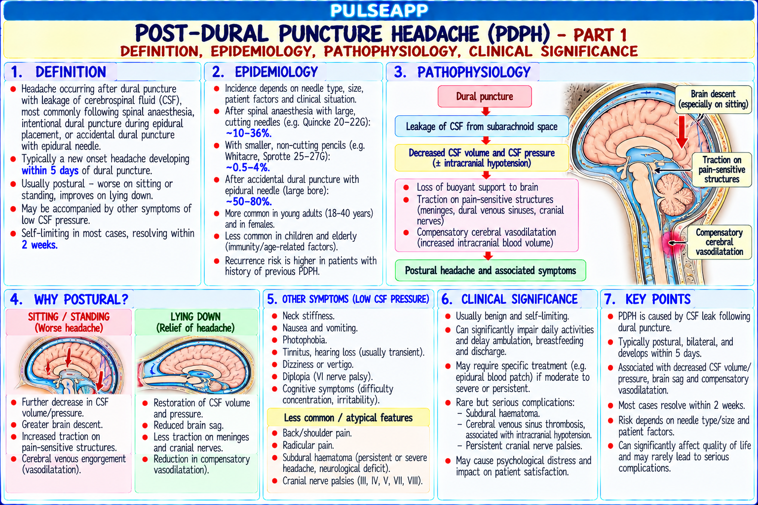
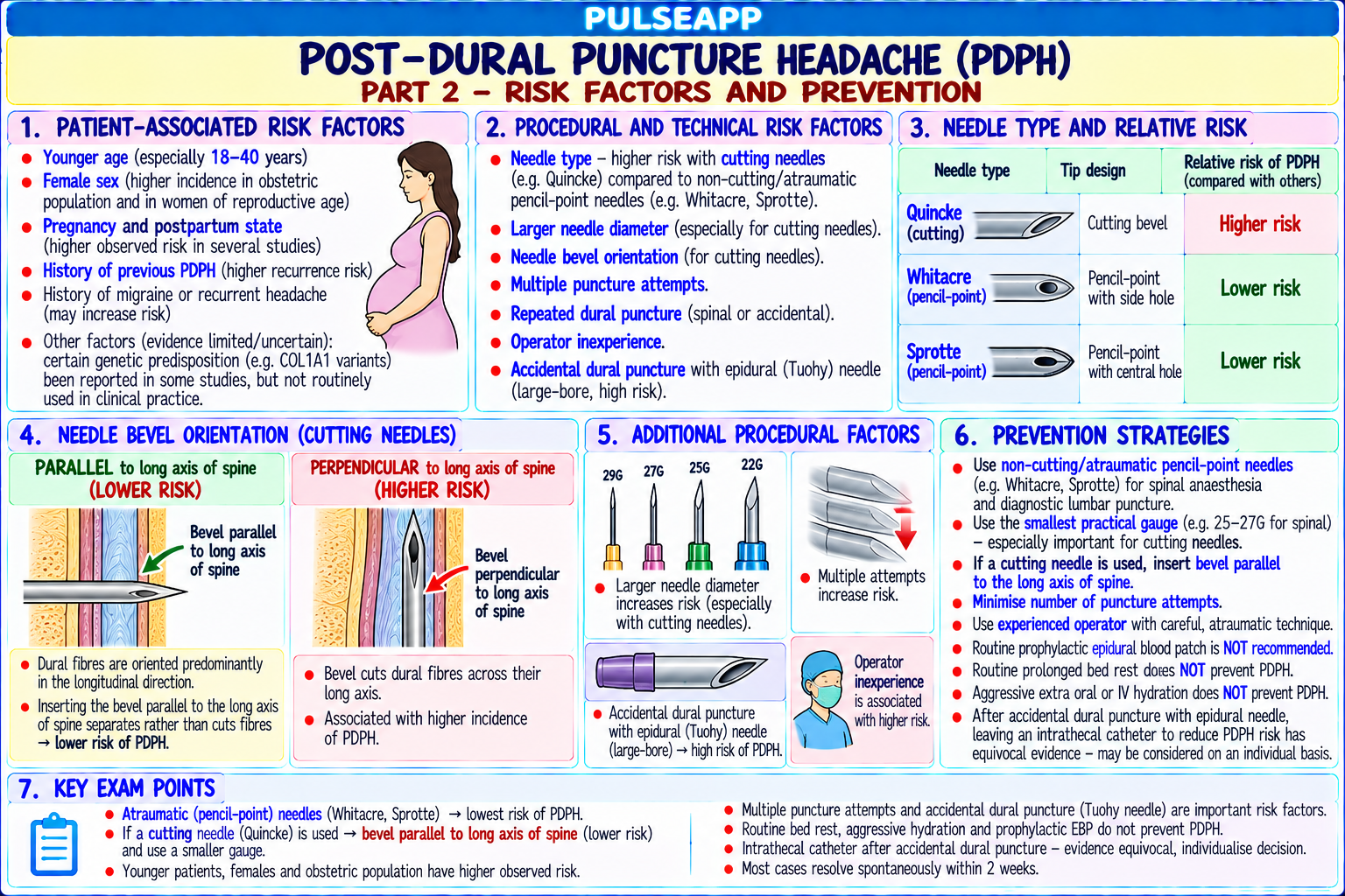
Describe the pathophysiology of post-dural puncture headache (PDPH). Outline the risk factors, clinical features, and diagnostic criteria. Describe the management protocol from conservative measures to definitive epidural blood patch (EBP) technique, contraindications, and efficacy.

collections Question Diagrams & Reference Images (2)
Question Reference Diagram
zoom_in View Image
Question Reference Diagram
zoom_in View Image
description Clinical Response
⚙ Core Concept
PDPH is the most common serious complication of spinal and epidural anaesthesia — occurring in up to 70–80% of patients after accidental dural puncture with a 16G Tuohy needle in obstetrics. Its characteristic postural worsening (sitting/standing → severe headache; lying flat → rapid relief) pathognomonically distinguishes it from other causes of post-procedure headache. The epidural blood patch (EBP) — injection of autologous blood into the epidural space at or below the dural puncture level — provides immediate, definitive relief in approximately 70–90% of patients. (Turnbull DK — BJA 2003; Safa-Tisseront V — EBP efficacy; Apfel CC — prevention of PDPH; AAGBI Guidelines; Yentis SM)
A. Pathophysiology2 marks

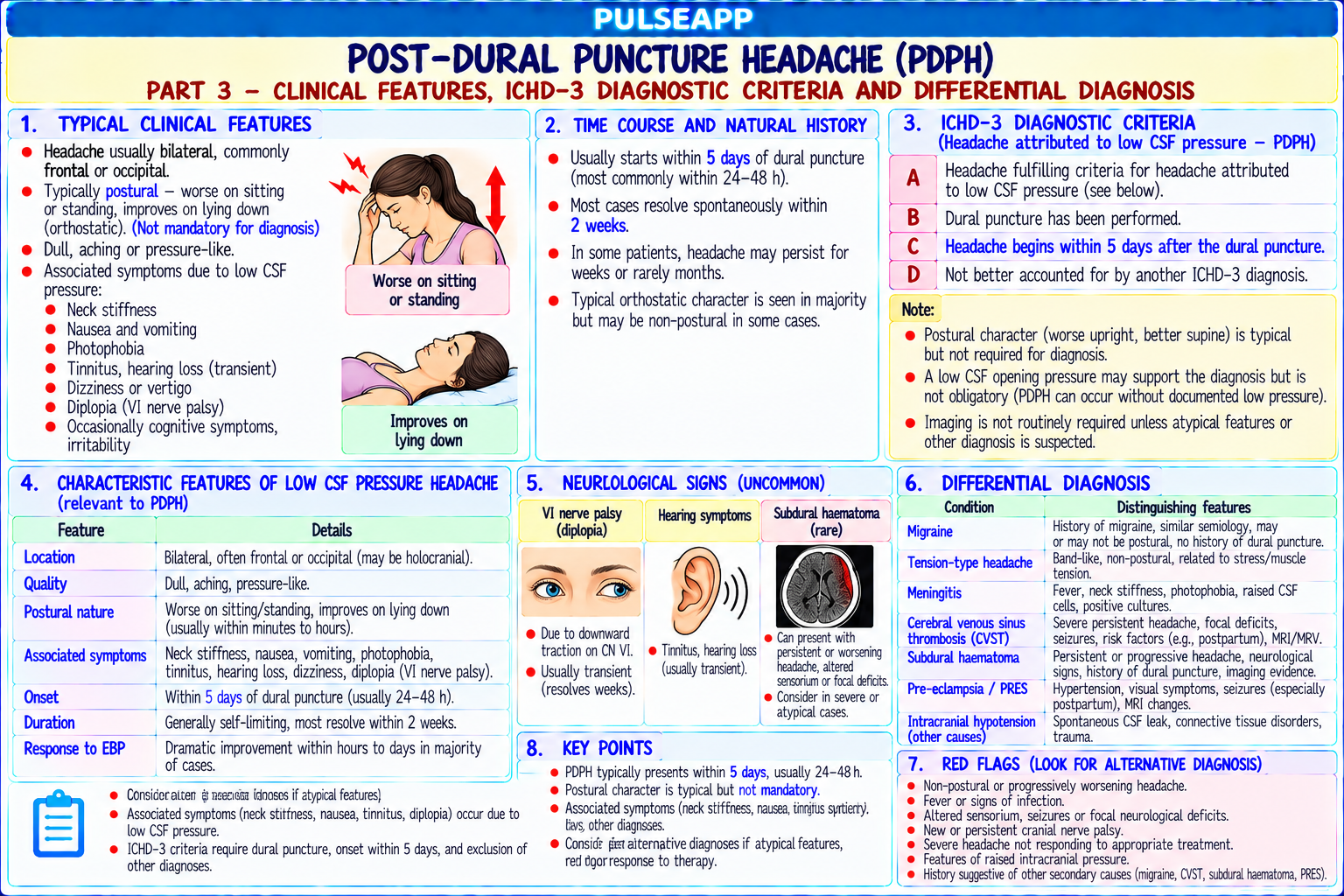
Dural puncture → CSF leak through the dural defect into the epidural space (at approximately 0.1–0.2 mL/min) → CSF volume in the subarachnoid space decreases → CSF pressure falls → the buoyant support of the brain in CSF is reduced → the brain descends slightly with gravity when upright → traction on pain-sensitive structures (the meningeal blood vessels, cranial nerves — particularly the trigeminal nerve = frontal/temporal headache, and the vagus and glossopharyngeal nerves = nausea and vomiting) → postural headache

The two mechanisms: (1) direct traction on pain-sensitive structures from CSF hypotension; (2) reflex cerebral vasodilation (adenosine-mediated) compensatory to the CSF loss — additional vascular headache component; the cerebral vasodilation component explains why caffeine (vasoconstrictor) provides partial temporary relief

IIH (intracranial pressure reduction): CSF pressure may fall from normal 10–15 cmH₂O to <5 cmH₂O; measured as "low opening pressure" on lumbar puncture

B. Risk Factors and Clinical Features2 marks

Risk Factor Effect Needle gauge Smaller gauge → smaller dural defect → less CSF leak → lower PDPH risk; 25G Whitacre: 1–2% PDPH; 22G Quincke: 25–30% PDPH; 16G

Tuohy (accidental ADP): 70–80% PDPH Needle type/design Pencil-point (Whitacre/Sprotte — separates rather than cuts dural fibres): much lower PDPH rate than cutting (Quincke); for equivalent gauge, pencil-point has 5× lower PDPH rate

Quincke bevel Bevel parallel to dural longitudinal fibres: lower PDPH rate (smaller functional defect); perpendicular: higher rate orientation

Age Young patients (especially obstetric population): high PDPH risk; elderly: lower risk (reduced CSF pressure and flow; more compliant meninges)

Gender Female: higher risk than male (hormonal differences and obstetric population); pregnancy further increases risk Previous PDPH Strong risk factor for recurrence — may reflect individual susceptibility in dural compliance Diagnostic criteria (IHS — International Headache Society): headache that develops within 5 days of dural puncture; worsens within 15 minutes of sitting/standing and resolves (or improves significantly) within 15 minutes of lying flat; accompanied by at least one of: neck stiffness, tinnitus, hypacusis, photophobia, nausea

Severity grades: mild (tolerated; no limitation of daily activities); moderate (limits daily activities; patient confined to bed part of the time); severe (complete bed rest; unable to ambulate); very severe (cranial nerve palsies — 6th nerve palsy from traction most common → diplopia)

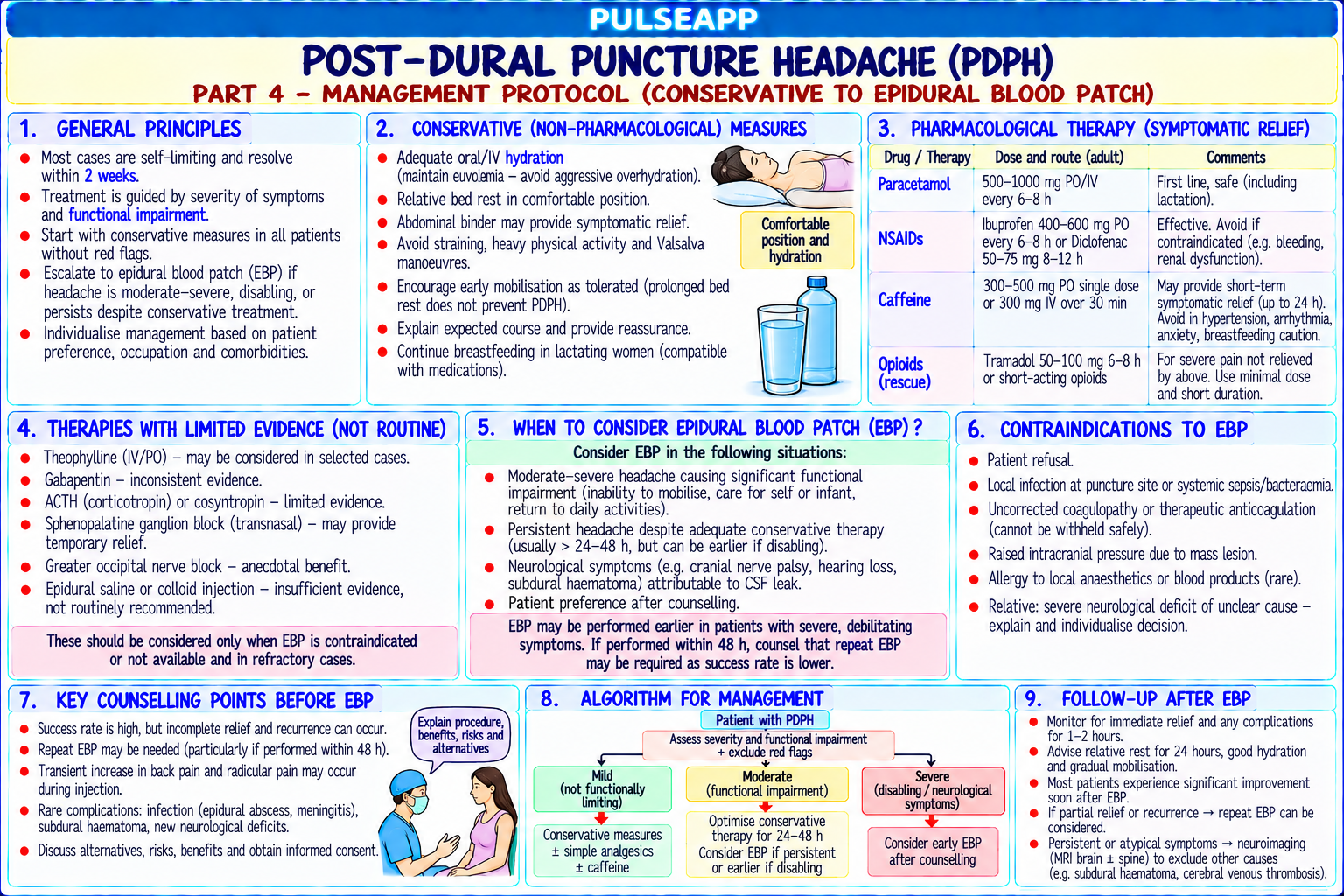
C. Conservative Management (First 24 Hours)2 marks

Bed rest: lying flat relieves the headache by reversing the gravitational traction; but strict bed rest does NOT reduce the rate of EBP requirement or speed recovery — provide for comfort only

Analgesics: paracetamol 1 g QID; NSAIDs (ibuprofen 400 mg TID); simple analgesics for symptomatic relief while awaiting natural dural sealing

IV/oral hydration: adequate hydration supports CSF production; no evidence that supernormal hydration accelerates recovery

Caffeine: caffeine sodium benzoate 500 mg oral or IV; causes cerebral vasoconstriction (adenosine antagonist) → reduces the vascular component of PDPH → temporary partial relief (12–24 hours); does NOT seal the dural hole; approximately 70% of patients report temporary improvement; reassess at 24 hours — if still symptomatic, EBP should be discussed

ACTH/Cosyntropin: ACTH 1.5 IU/kg IV once → stimulates adrenal cortisol production → increases CSF production (aldosterone effect on choroid plexus); some trials showing modest benefit; not widely used

Sumatriptan: some evidence in case reports; not standard treatment

Reassurance: PDPH naturally resolves in most patients within 7–14 days as the dural hole heals; 85% of patients improve without EBP if managed conservatively for 14 days

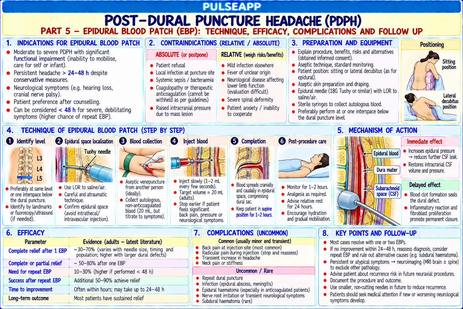
D. Epidural Blood Patch (EBP)4 marks
✅ Epidural Blood Patch — The Definitive Treatment for PDPH
Indications Moderate-to-severe PDPH not controlled by 24 hours of conservative treatment; cranial nerve palsy (6th nerve palsy → ophthalmology involvement; EBP urgently); patient requesting earlier intervention after informed discussion of risks and natural history Technique 1. Informed consent; discuss the 70–90% first-EBP success rate; mention 10–30% require a second EBP 2. Aseptic technique throughout; patient lateral decubitus (side easier for both the epidural and the blood draw) 3. Insert 16G Tuohy epidural needle at the SAME or ONE SPACE BELOW the original dural puncture level (ensures blood reaches and seals the dural defect) 4. Confirm epidural placement with loss of resistance to saline 5. Assistant aseptically draws 20 mL autologous blood from the patient's antecubital vein (while you maintain epidural needle position); a second assistant assists if needed 6. Slowly inject 15–20 mL autologous blood into the epidural space (stop if the patient reports pain, paraesthesiae, or significant discomfort — these indicate nerve root compression; typically 15 mL is achievable) 7. Ask the patient to lie flat (supine or lateral) for 30–60 minutes post-EBP to allow blood to clot and form a "patch" over the dural hole 8. Do NOT perform back exercises or Valsalva manoeuvres for 48 hours (risk of dislodging the clot before it matures into fibrous tissue) Mechanism of Efficacy Injected blood clots over the dural defect → initially seals the leak mechanically → fibrin deposition → permanent dural sealing within 6–12 hours; simultaneously, the blood volume in the epidural space transiently raises the CSF pressure (epidural blood compresses the dural sac → CSF is pushed cranially → CSF pressure rises → immediate relief of the traction headache within minutes of injection) Contraindications Active systemic infection or local infection at the injection site (septicaemia — injecting infected blood → epidural abscess) Coagulopathy (bleeding into epidural space → epidural haematoma) Patient refusal Raised intracranial pressure (a rare contraindication where EBP may cause dangerous ICP spike)
🎤 Viva Corner
Q. Why do you inject EBP at the same or one level BELOW the dural puncture, not above it?
The anatomical rationale for injecting EBP at or below the level of the original dural puncture is based on the direction of spread of the injected blood within the epidural space. When blood is injected into the epidural space, it spreads both cephalad and caudad from the injection site, but the cephalad spread is greater due to the normal slight negative epidural pressure, the pressure of injection, and the tendency for blood to track along fascial planes toward the thoracic epidural space where there is more available volume. If the EBP were performed above the dural puncture level, the blood would preferentially spread further cephalad — away from the dural defect — and the volume reaching the puncture site would be reduced, potentially resulting in incomplete sealing and treatment failure. By injecting at the same level or one space below: the cephalad spread of blood from the injection point travels directly to and past the dural defect level, ensuring maximum blood contact with the puncture hole; the blood clot forms directly over the defect in the most reliable manner. The ONE LEVEL BELOW approach also has the advantage of avoiding re-puncture at exactly the site of the previous accidental dural puncture — which may have some residual dural weakness — and allows the blood to spread upward to cover the defect without requiring the Tuohy needle to be placed at the exact puncture site. In practice, many anaesthesiologists attempt to place the EBP at exactly the same interspace as the original puncture when the level is known precisely, or one level below when there is uncertainty about the exact level of accidental dural puncture (which is particularly relevant after labour epidurals where the exact level may not have been precisely recorded).
★ Examiner's Pearl
PDPH risk by needle gauge (25G Whitacre 1–2%; 16G Tuohy ADP 70–80%) with the needle type comparison (pencil-point vs cutting — 5× lower PDPH rate for pencilpoint) are the specific numeric facts tested. EBP volume (15–20 mL autologous blood) and the insertion level (same or one level below the dural puncture) are the specific technique facts. The dual mechanism of EBP (mechanical sealing of dural defect + transient CSF pressure rise relieving traction) explains both the immediate relief (CSF pressure normalises within minutes) and the sustained benefit (dural sealing over 6–12 hours).
Turnbull DK, Shepherd DB. Post-dural puncture headache — pathogenesis, prevention and treatment (BJA 2003;91:718-729). Safa-Tisseront V et al. Effectiveness of epidural blood patch in PDPH (Anesthesiology 2001;95:334-339). Apfel CC et al. Prevention of postdural puncture headache after accidental dural puncture — a quantitative systematic review (BJA 2010;105:255-263). AAGBI. Accidental dural puncture and PDPH 2018. Miller RD et al. Miller's Anaesthesia, 9th Ed.
lock Protected Clinical Document • Pulse App • Screenshots Strictly Prohibited
QUESTION 88 person Asked by .
bookmark_add

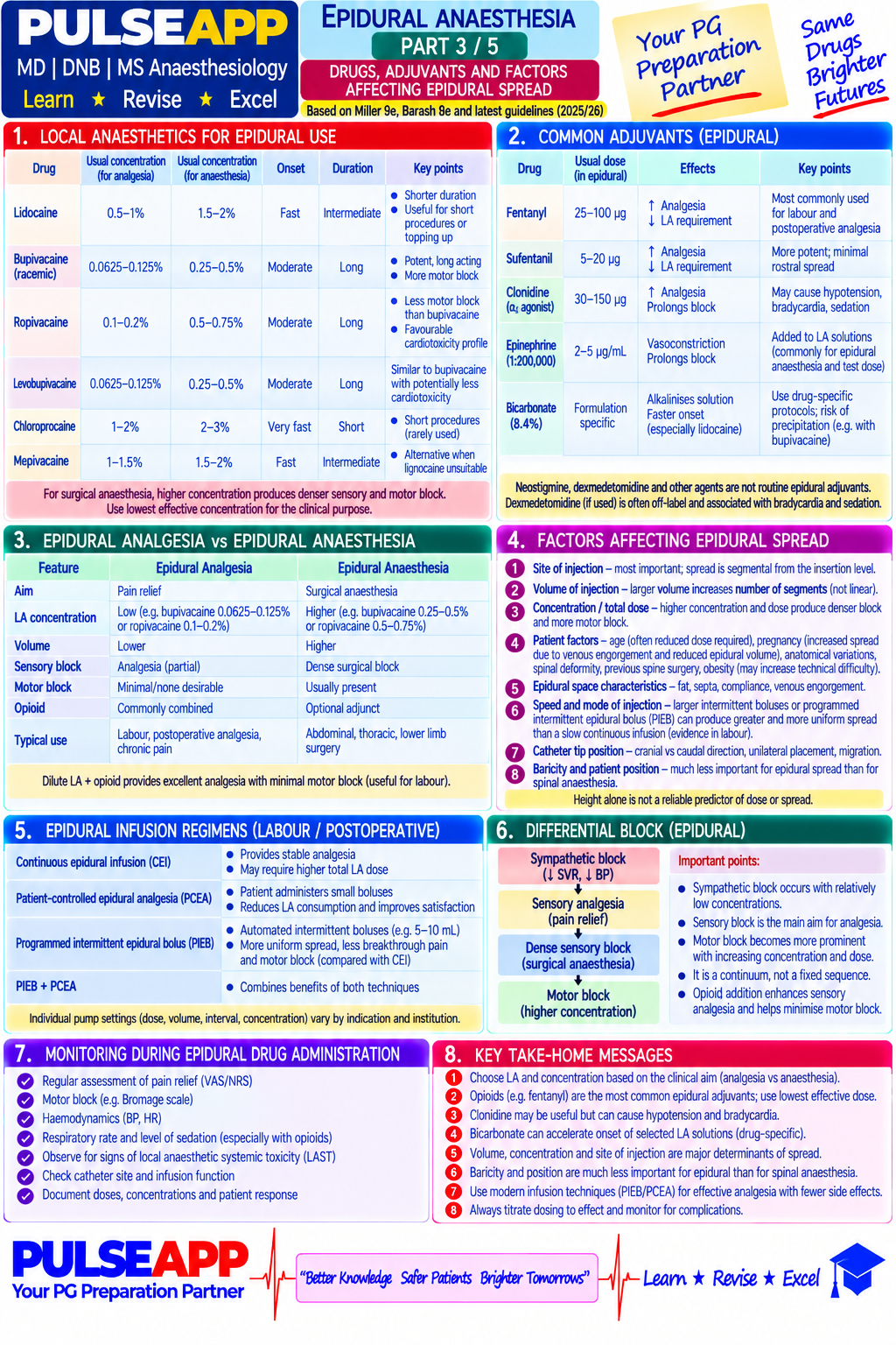
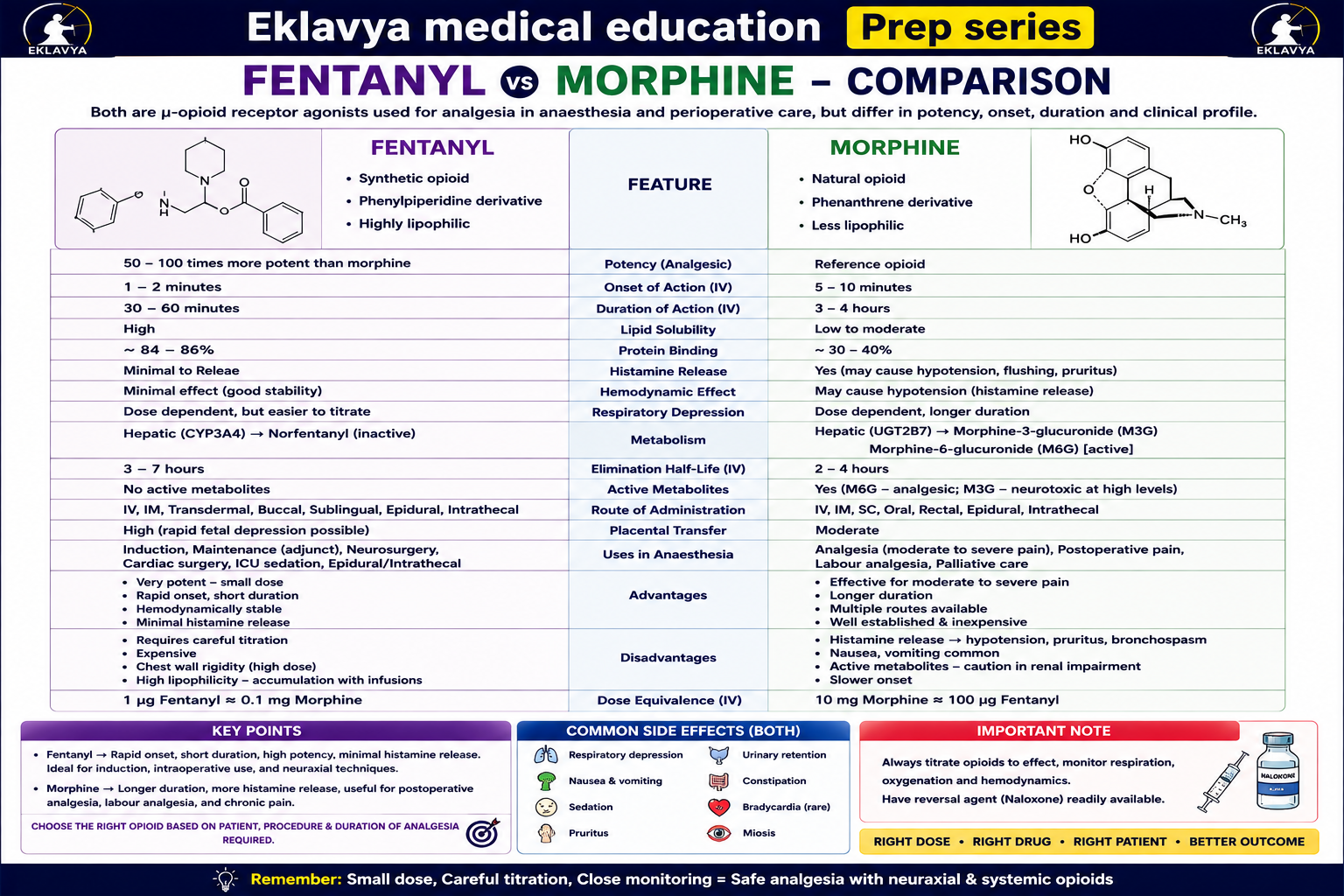
Describe how neuraxial opioids produce analgesia. Compare fentanyl vs morphine — onset, spread, duration, and safety profile. State specific intrathecal and epidural doses for CS and major surgery. Outline the monitoring and management of delayed respiratory depression from intrathecal morphine.

collections Question Diagrams & Reference Images (2)
Question Reference Diagram
zoom_in View Image
Question Reference Diagram
zoom_in View Image
description Clinical Response
⚙ Core Concept
Neuraxial opioids act directly at mu-opioid receptors in the dorsal horn — the single most specific site of opioid analgesia — providing powerful analgesia without motor or sympathetic block. Lipid solubility determines onset, spread, and the critical safety difference: lipophilic fentanyl stays local; hydrophilic morphine spreads in the CSF to reach the respiratory centre 6–24 hours later. (Cousins MJ, Mather LE — Anesthesiology 1984; Chaney MA — Can J Anaesth 1995; Sultan P et al. — BJA 2013)
A. Mechanism of Neuraxial Opioid Analgesia2 marks

Site of action: mu-opioid receptors (MOR) in the substantia gelatinosa (laminae I and II) of the dorsal horn; PRESYNAPTIC: opioid binds MOR on C/Aδ fibre terminals → ↓ Ca²⁺ influx → ↓ release of substance P, glutamate, CGRP → reduced nociceptive transmission; POSTSYNAPTIC: ↑ K⁺ conductance → hyperpolarisation → reduced responsiveness to nociceptive input The dual mechanism provides potent, segmental analgesia without affecting motor, sympathetic, or non-pain sensory modalities — the key clinical advantage over LA agents

B. Lipophilic vs Hydrophilic — Key Comparison3 marks

Property Fentanyl (lipophilic, log P 4.05) Morphine (hydrophilic, log P 0.9) Onset 5–15 minutes (rapidly absorbed into spinal cord 30–60 minutes (slow diffusion through aqueous CSF) lipid) Duration 2–4 hours (rapid redistribution out of cord) 12–24 hours (persists in CSF; slow clearance)

CSF spread Minimal — absorbed before spreading rostrally Extensive — remains in CSF → bulk flow cephalad to brainstem

Delayed respiratory Minimal — early (0–4h) from systemic absorption HIGH RISK at 6–24 hours — morphine accumulates near respiratory centre in depression only medulla

Systemic vascular uptake High — much of epidural fentanyl is systemic, not Low — primarily spinal mechanism spinal IT dose (adult) 20–25 mcg added to spinal LA 100–300 mcg (100–150 mcg for CS; up to 300 mcg for major surgery) Epidural dose 50–100 mcg bolus; 2–4 mcg/mL infusion 2–4 mg epidural; 0.05–0.1 mg/mL infusion

C. Clinical Applications & Doses2 marks

Scenario Recommended Drug Dose Benefit Caesarean section Morphine 100–150 mcg + Fentanyl Added to hyperbaric bupivacaine 2 mL Morphine: 12–24h post-CS analgesia; Fentanyl: augments — IT 20–25 mcg intraoperative block quality Major orthopaedic Morphine 200–300 mcg Added to spinal LA 18–24h postoperative analgesia; reduces opioid surgery — IT requirements

Labour analgesia — Fentanyl 2 mcg/mL in dilute LA Bupivacaine 0.0625–0.1% + fentanyl 2 Walking epidural; dense block without motor impairment epidural mcg/mL at 5–10 mL/hr Post-thoracotomy — Fentanyl or sufentanil 0.5 mcg/mL in 5–8 mL/hr thoracic epidural infusion Facilitates extubation; reduces PPCs epidural ropivacaine 0.2%

D. Monitoring & Management of Delayed Respiratory Depression3 marks

Mechanism: morphine slowly migrates cephalad in CSF via bulk flow over 6–12 hours → reaches the fourth ventricle near the pre-Bötzinger complex (respiratory rhythm generator) → mu-receptor activation → ↓ respiratory drive → progressive hypoventilation → hypoxia

Risk factors: IT morphine >300 mcg; co-administered systemic opioids/sedatives; elderly; obesity/OSA; poor respiratory reserve

Mandatory monitoring: hourly RR and sedation score for 24 hours; SpO₂ monitoring; supplemental O₂ available; naloxone at bedside; monitored ward (HDU level)

Treatment: RR <8 or SpO₂ <90%: naloxone 0.04–0.4 mg IV titrated (start 0.04 mg increments to preserve analgesia); then naloxone infusion 2–5 mcg/kg/hr (morphine duration exceeds naloxone t½ of 45–90 min → re-narcotisation without infusion)

E. Side Effects —

Pruritus: 50–100% incidence with IT morphine; direct MOR activation in trigeminal nucleus → facial and truncal itch; treat: ondansetron 4 mg IV (5-HT3 antagonism), nalbuphine 5–10 mg IV, or low-dose naloxone 0.04 mg IV

PONV: 20–40%; multimodal prophylaxis; ondansetron at emergence

Urinary retention: sacral MOR activation → detrusor relaxation; catheterise if symptomatic

🎤 Viva Corner
Q. A post-CS patient who received IT morphine 150 mcg is found at 14 hours post-op with RR 6/min and SpO₂ 88%. Immediate management?
This is delayed respiratory depression from intrathecal morphine. RR 6 and SpO₂ 88% requires immediate action. Call for help. Apply 15 L/min O₂ by face mask immediately. Stimulate the patient verbally — opioid-depressed patients often temporarily improve their RR with stimulation, buying time. Administer naloxone 0.04 mg IV incrementally every 2–3 minutes titrating to RR ≥12/min — use small doses to avoid complete analgesia reversal in a post-CS patient. Critical pharmacokinetic point: naloxone t½ is 45–90 minutes, far shorter than intrathecal morphine duration (12–24h) → when naloxone wears off, respiratory depression recurs (re-narcotisation); therefore, start a naloxone infusion at 2–5 mcg/kg/hr IV and continue for 8–12 hours in an HDU/ICU setting with continuous SpO₂ monitoring. If SpO₂ does not improve despite naloxone and O₂: bag-mask ventilation; if required, intubate and ventilate until morphine effect dissipates. Document the event and review the monitoring protocol — hourly RR observation should have detected this before SpO₂ reached 88%.
★ Examiner's Pearl
Lipophilic vs hydrophilic comparison with specific numbers (fentanyl: onset 5 min, duration 2–4h, minimal CSF spread; morphine: onset 30–60 min, duration 12–24h, extensive spread, delayed respiratory depression 6–24h). IT morphine doses (CS: 100–150 mcg; major surgery: up to 300 mcg). Naloxone infusion for re-narcotisation (2–5 mcg/kg/hr — because naloxone t½ < morphine duration).
Cousins MJ, Mather LE. Intrathecal and epidural administration of opioids (Anesthesiology 1984;61:276-310). Sultan P et al. Meta-analysis of IT morphine for CS (BJA 2013). Chaney MA. Side effects of neuraxial opioids (Can J Anaesth 1995). AAGBI Epidural Monitoring Guidelines 2020.
lock Protected Clinical Document • Pulse App • Screenshots Strictly Prohibited
QUESTION 89 person Asked by .
bookmark_add

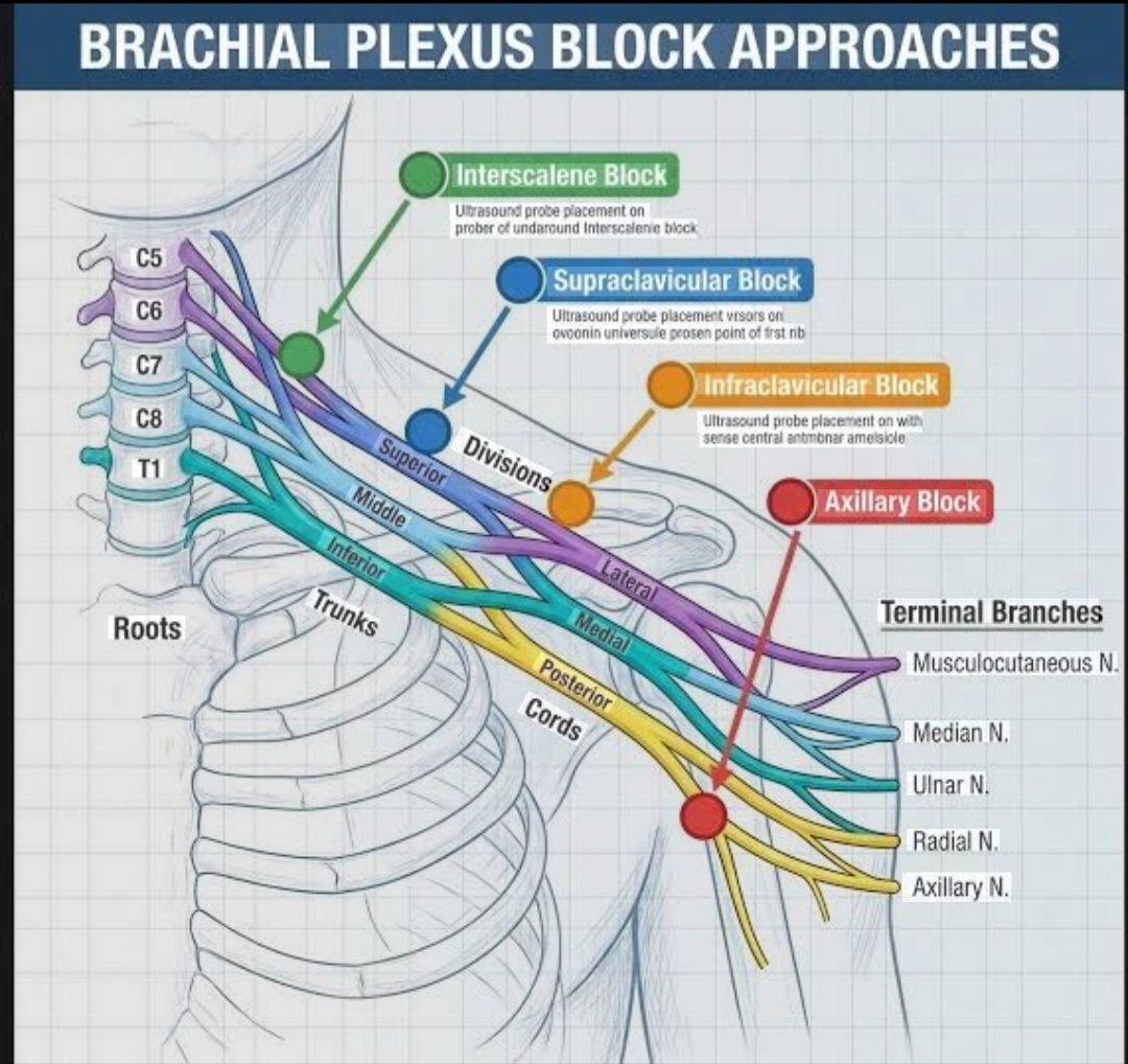
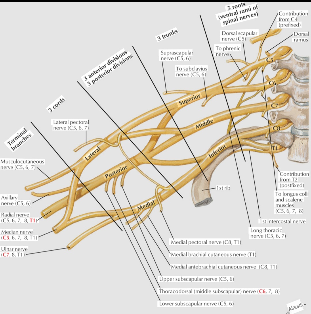
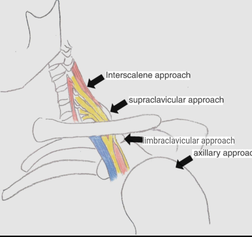
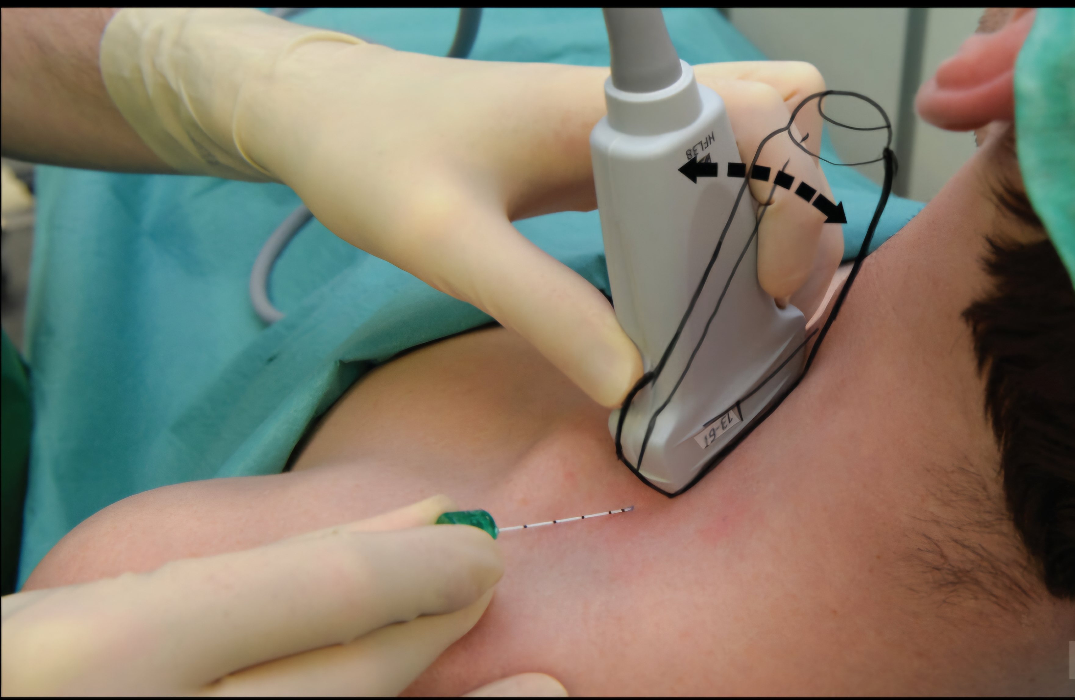
Describe brachial plexus anatomy at the supraclavicular level. Outline the ultrasound-guided technique including the corner pocket injection. State indications and specific complications — pneumothorax, phrenic nerve palsy, Horner's syndrome.

collections Question Diagrams & Reference Images (9)
Question Reference Diagram
zoom_in View Image
Question Reference Diagram
zoom_in View Image
Question Reference Diagram
zoom_in View Image
Question Reference Diagram
zoom_in View Image
Question Reference Diagram
zoom_in View Image
Question Reference Diagram
zoom_in View Image
Question Reference Diagram
zoom_in View Image
Question Reference Diagram
zoom_in View Image
Question Reference Diagram
zoom_in View Image
description Clinical Response
⚙ Core Concept
The supraclavicular brachial plexus block — often called the "spinal of the upper limb" — targets the compactly arranged trunks just posterolateral to the subclavian artery, providing a reliable single-injection block for the entire upper limb below the shoulder. The "corner pocket" injection specifically targets the inferior trunk, preventing the most common failure (incomplete ulnar nerve coverage). (Tran DQ — Reg Anesth 2010; Perlas A — Acta Anaesthesiol 2003; Hadzic A — Regional Anaesthesia)
A. Anatomy at the Supraclavicular Level2 marks

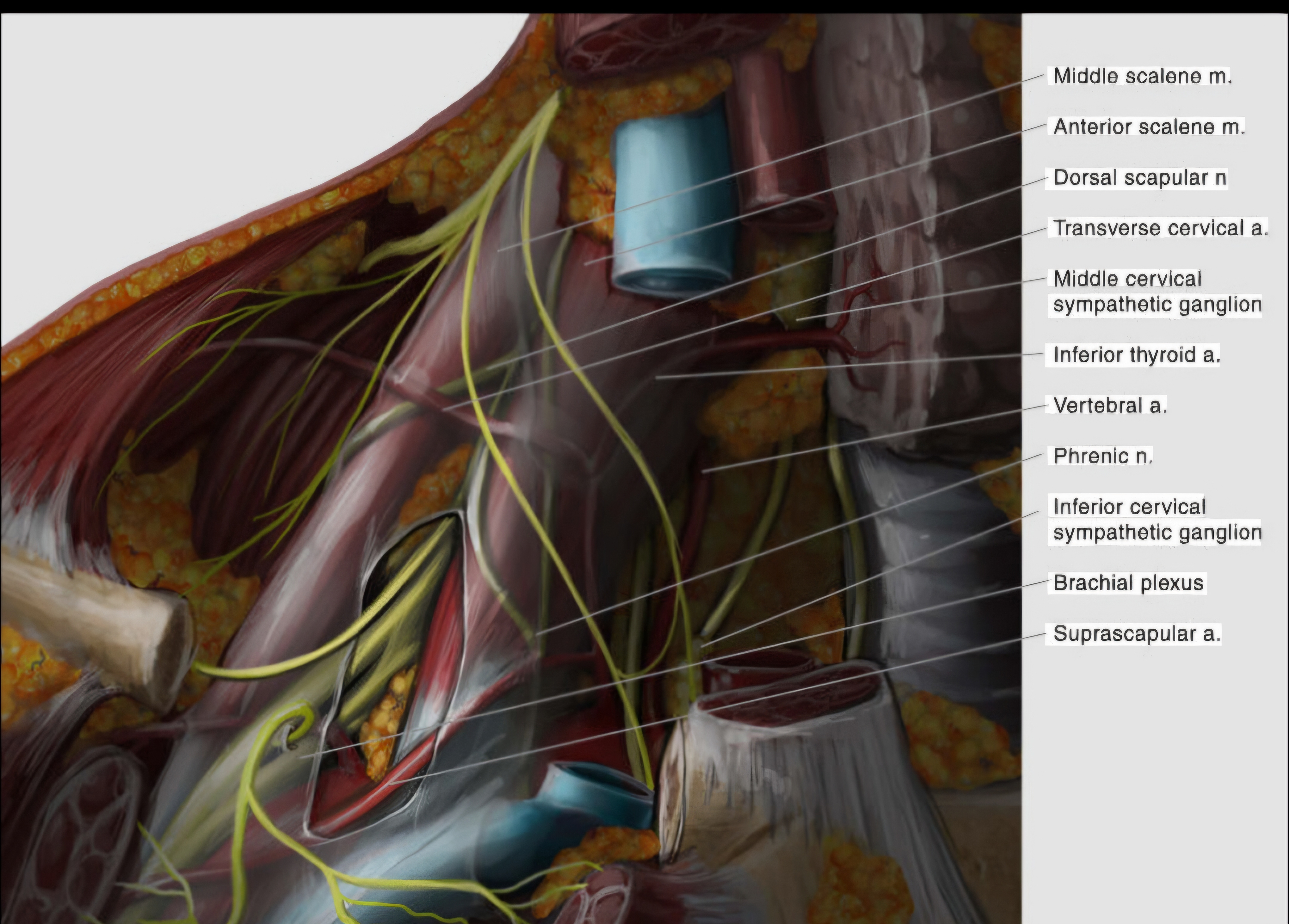
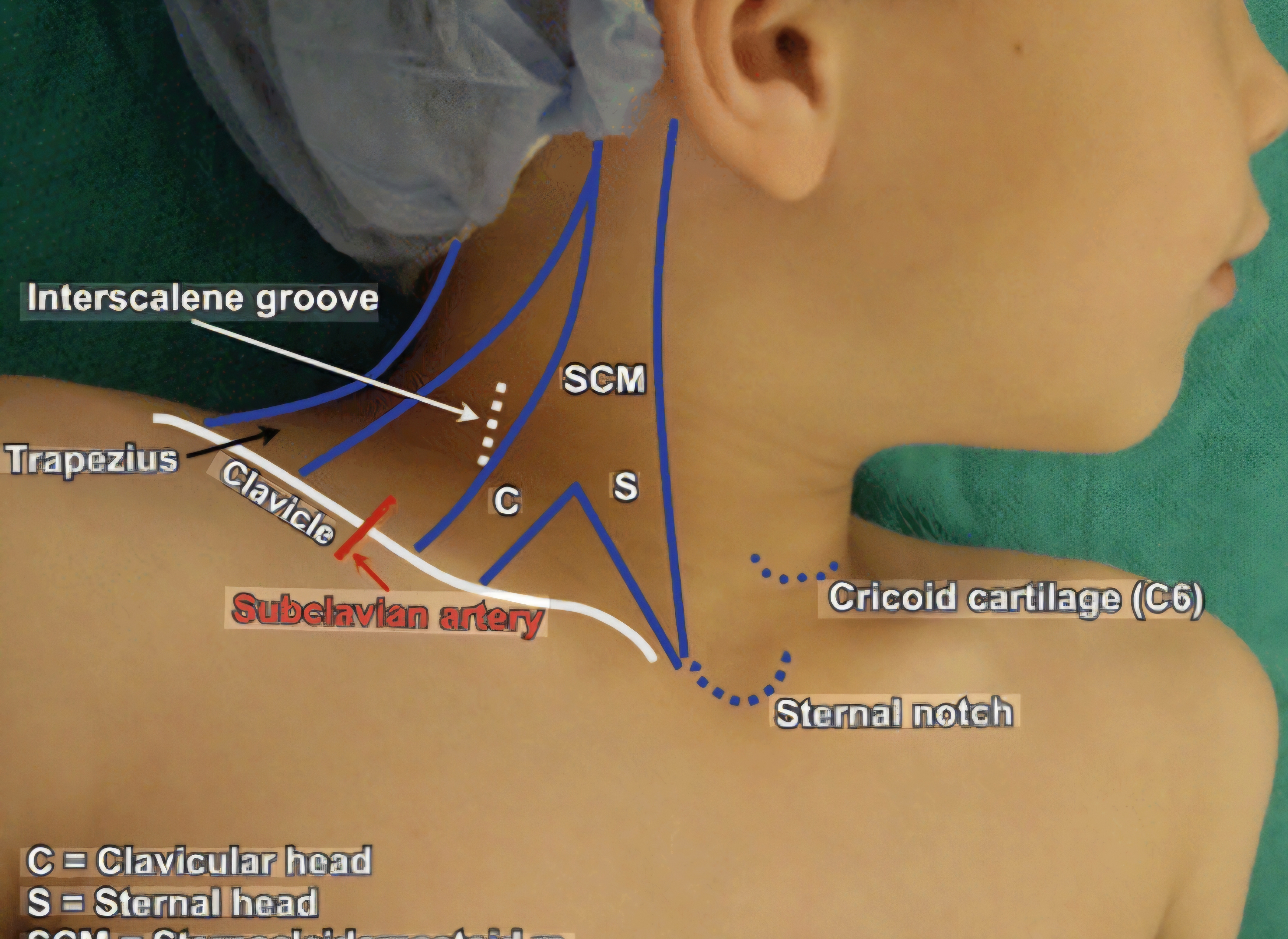
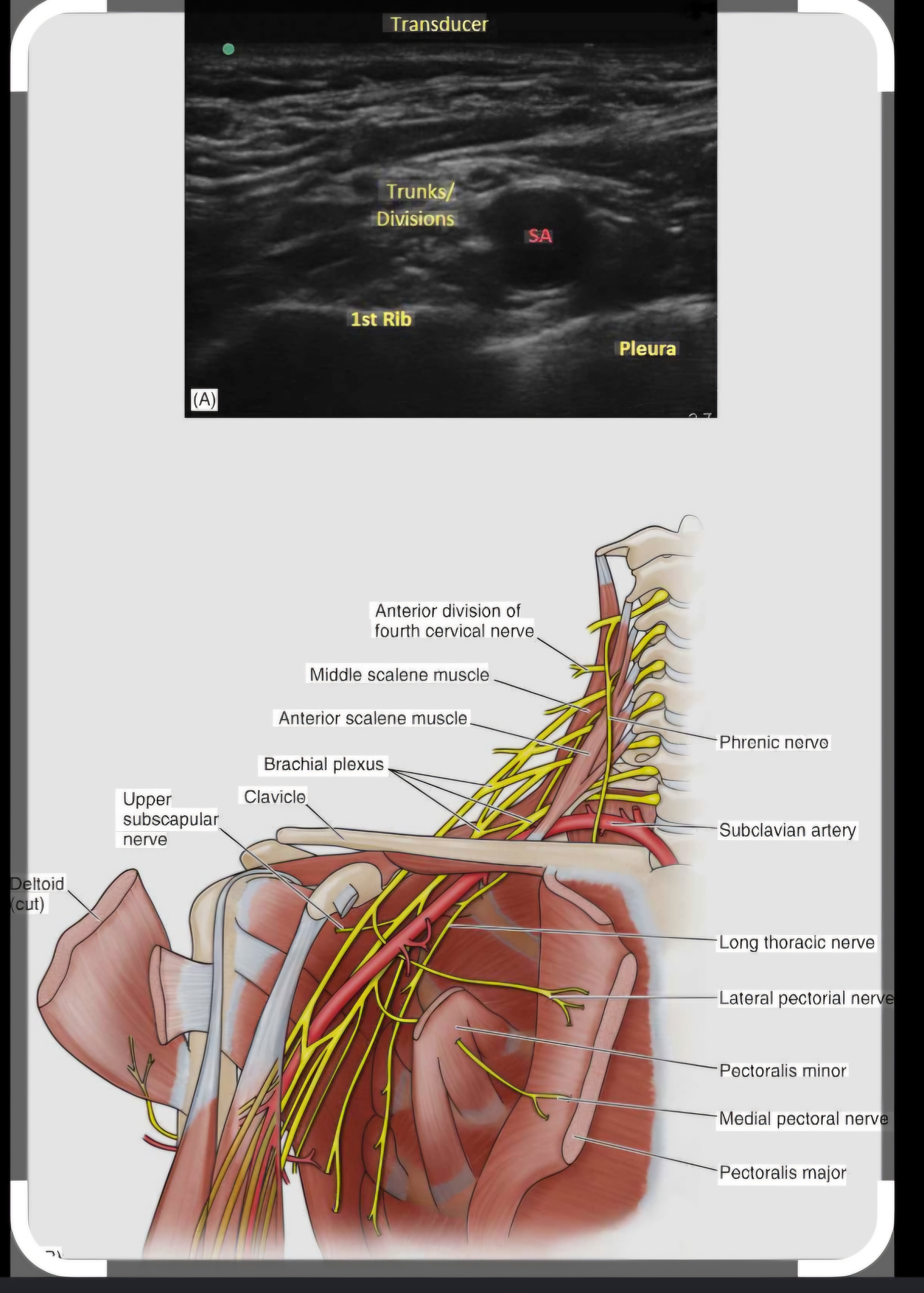
At the supraclavicular level, the brachial plexus roots C5–T1 have formed into three TRUNKS: superior (C5–C6), middle (C7), inferior (C8–T1); they lie compactly as a cluster posterolateral to the subclavian artery, above the first rib, deep to the clavicle

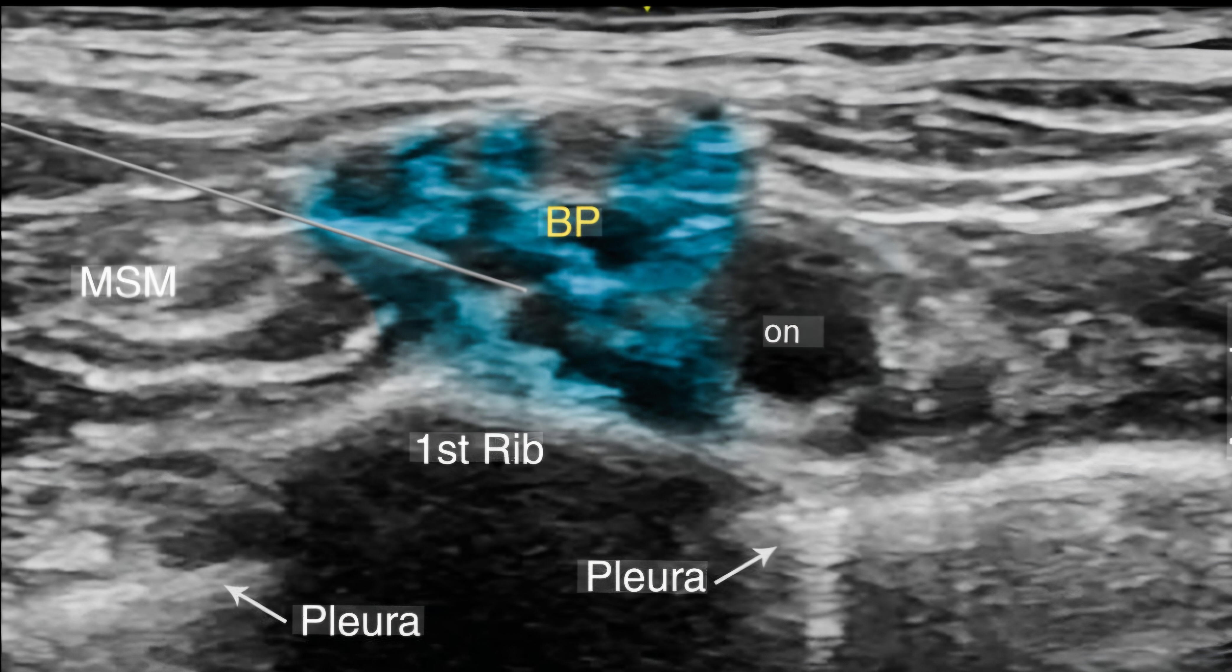
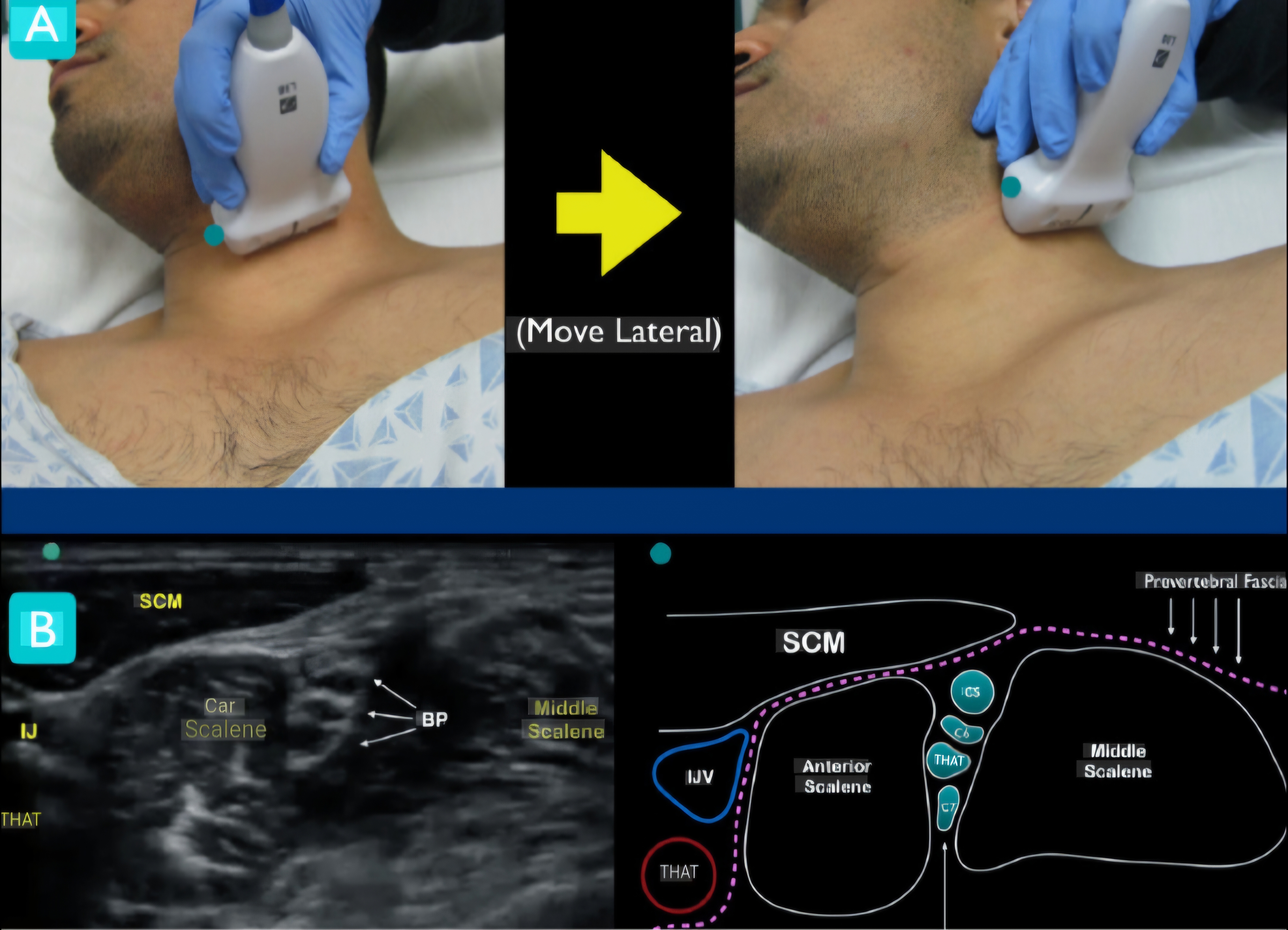
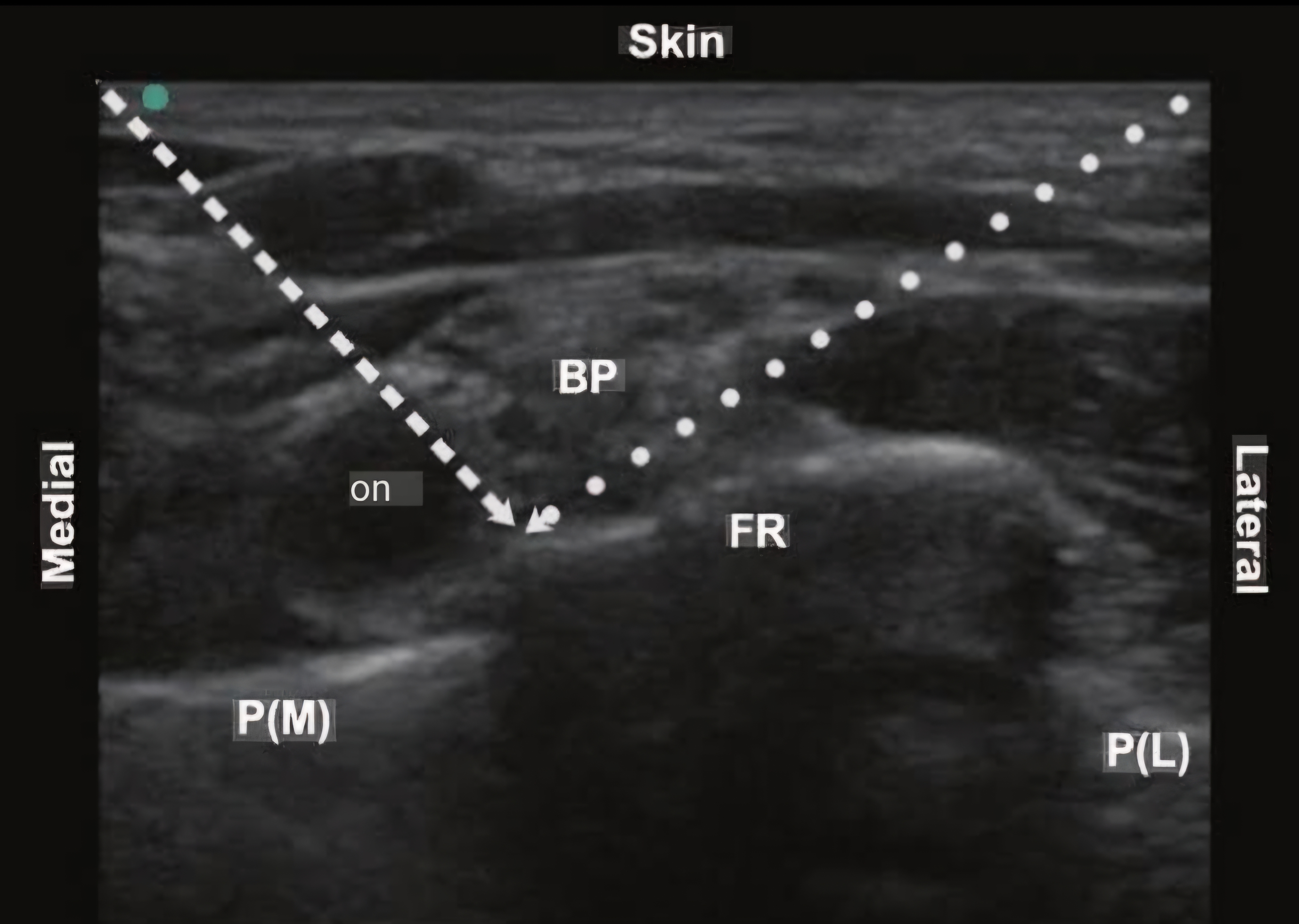
Sonoanatomy: high-frequency linear probe (10–15 MHz) in the supraclavicular fossa, coronal oblique plane; the subclavian artery appears as a large pulsatile anechoic circle; the brachial plexus trunks appear as a "bunch of grapes" — hypoechoic cluster — posterolateral to the artery; the first rib is a bright hyperechoic line with acoustic shadow deep to the plexus; pleura visible just deep to the first rib The "corner pocket": the zone at the corner between the lateral border of the subclavian artery and the superior surface of the first rib; the inferior trunk (C8– T1 → ulnar nerve) sits specifically here; targeted injection in this corner ensures complete block of all three trunks including the ulnar nerve territory — the most commonly missed nerve with supraclavicular techniques

B. Technique2 marks

1. Patient supine, head turned 45° away; high-frequency probe in supraclavicular fossa; coronal oblique plane 2. In-plane needle approach lateral to medial; 22G 50 mm needle; advance toward the corner pocket first (lateral subclavian artery border + first rib superior surface) 3. Hydrolocation: 1–2 mL saline to confirm tip position (fluid surrounds inferior trunk in the corner; if fluid goes deep to first rib → withdraw — pleural puncture risk) 4. Inject 5–10 mL LA into the corner pocket (inferior trunk coverage); then reposition needle superiorly and inject 15–20 mL more to cover superior and middle trunks; total 20–30 mL 0.375% ropivacaine or 0.25% bupivacaine

C. Complications4 marks

Complication Incidence Mechanism Management Pneumothorax 4% landmark; <0.5% Pleura is immediately deep to the first rib — the deep margin of Small (<15%) — O₂ + observation; Large (>15%) or ultrasound-guided the injection target; needle past first rib → pleural puncture → symptomatic → chest drain; CXR if any respiratory delayed pneumothorax (may present 1–6 hours post-block) symptoms develop post-block Phrenic nerve 40–60% standard Phrenic nerve lies on the anterior scalene adjacent to the Clinically inconsequential with normal contralateral palsy volumes; 20–30% brachial plexus; LA spreads medially → baths the phrenic function; CONTRAINDICATED if: contralateral phrenic with reduced volumes nerve → ipsilateral hemidiaphragm paralysis → ↓ FVC 25% palsy, contralateral pneumonectomy, severe COPD (FEV1 (5–10 mL) <50%) Horner's 1–4% Stellate ganglion (T1 sympathetic) adjacent to plexus; LA Benign and self-limiting; reassure patient (warn them Syndrome spreads medially → sympathetic chain block → ipsilateral preoperatively) ptosis, miosis, anhidrosis LAST <1% with US Large LA volume adjacent to subclavian artery; intravascular Incremental injection with aspiration every 5 mL; LAST guidance injection protocol

D. Indications vs Other Upper Limb Blocks2 marks

Best for: surgery from the elbow to the hand; forearm fractures; wrist/hand surgery; more reliable than axillary block for elbow procedures (musculocutaneous nerve reliably blocked at this level); more reliable ulnar coverage than interscalene (with corner pocket technique)

Compared to interscalene: supraclavicular has less phrenic nerve palsy risk (though still 20–30%); better ulnar nerve coverage; less good for true shoulder surgery (interscalene preferred) Intercostobrachial nerve NOT covered (medial upper arm skin from T2); supplement with subcutaneous ring injection if medial arm tourniquet is planned

🎤 Viva Corner
Q. Why is the corner pocket specifically targeted for the supraclavicular block, and what clinical problem does it solve?
The corner pocket targets the inferior trunk (C8–T1) which sits at the angle formed by the lateral border of the subclavian artery and the superior surface of the first rib — this anatomically protected corner is inferior and medial to the main superior/middle trunk cluster that is more easily visualised by ultrasound. When anaesthesiologists inject only into the superior or lateral plexus cluster, the LA reliably blocks the superior (C5–C6) and middle (C7) trunks — providing good thumb, index, and middle finger analgesia — but the inferior trunk in the corner receives inadequate drug distribution, resulting in incomplete block of the ulnar nerve territory (ring and little finger, hypothenar eminence, medial forearm — the C8–T1 distribution). By specifically targeting the corner pocket with the first 5–10 mL of LA, the inferior trunk is bathed in drug before repositioning to cover the superior trunks. Studies show this corner pocket approach increases complete ulnar nerve block success from approximately 80% to 95%, eliminating the most common failure pattern of supraclavicular blocks.
★ Examiner's Pearl
"Bunch of grapes" sonoanatomy (hypoechoic cluster posterolateral to subclavian artery). Corner pocket = angle between lateral subclavian artery + superior first rib = inferior trunk = ulnar nerve coverage — this three-step chain. Pneumothorax risk reduced from 4% (landmark) to <0.5% (ultrasound) — the most important safety argument for US-guided technique.
Tran DQ et al. Corner pocket injection (Reg Anesth Pain Med 2010;35:109-113). Perlas A et al. US guidance improves BPB success (Acta Anaesthesiol Scand 2003). Kessler J et al. Phrenic nerve block with supraclavicular approach (Reg Anesth 2008). Hadzic A. Hadzic's Textbook of Regional Anesthesia, 3rd Ed.
lock Protected Clinical Document • Pulse App • Screenshots Strictly Prohibited
QUESTION 90 person Asked by .
bookmark_add

Describe interscalene anatomy (C5–C6 roots between anterior and middle scalene). Explain why phrenic nerve palsy is 100% at this level. State absolute contraindications and specific indications for shoulder surgery. Outline complications including vertebral artery and spinal cord risks.

collections Question Diagrams & Reference Images (4)
Question Reference Diagram
zoom_in View Image
Question Reference Diagram
zoom_in View Image
Question Reference Diagram
zoom_in View Image
Question Reference Diagram
zoom_in View Image
description Clinical Response
⚙ Core Concept
The interscalene block targets the brachial plexus at the root/early trunk level in the groove between the anterior and middle scalene muscles — providing the most reliable shoulder anaesthesia. However, the phrenic nerve runs directly on the anterior scalene at this level, making 100% ipsilateral hemidiaphragm paralysis unavoidable at standard volumes. (Urmey WF — Anesth Analg 1991; Stundner O — Reg Anesth 2015; Hadzic A)
A. Anatomy2 marks

The interscalene groove lies between the anterior scalene muscle (anteriorly) and the middle scalene muscle (posteriorly); the brachial plexus roots C5, C6, and C7 exit the intervertebral foramina and enter this groove at approximately the C6 level (cricoid cartilage level)

Sonoanatomy — "traffic light sign": high-frequency linear probe transversely at C6 level; the three roots C5, C6, C7 appear as three hypoechoic oval structures stacked between the anterior and middle scalene muscles — resembling traffic lights; the vertebral artery is deep (anteromedial) and must be identified and avoided; the internal jugular vein and carotid artery are medial

Critical relation: the phrenic nerve (C3–C4–C5) lies directly on the ANTERIOR SURFACE of the anterior scalene at this level; any injection sufficient to block C5–C6 roots simultaneously bathes the adjacent phrenic nerve

B. Why 100% Phrenic Nerve Palsy2 marks

The phrenic nerve forms from C3–C4–C5 roots and descends on the anterior surface of the anterior scalene muscle; at the C5–C6 interscalene level, the phrenic nerve is anatomically inseparable from the brachial plexus injection target — it lies on the muscle surface directly adjacent to the C5–C6 roots Any volume of LA sufficient to block C5–C6 (the primary targets) inevitably spreads anteriorly to the phrenic nerve; Urmey (Anesth Analg 1991) demonstrated by hemidiaphragm ultrasound that 100% of patients have ipsilateral hemidiaphragm paralysis after interscalene block regardless of technique or volume

Clinical consequence: ipsilateral hemidiaphragm paralysis → ↓ FVC ~25%; well tolerated in patients with normal contralateral function; catastrophic if contralateral reserve is limited

C. Absolute Contraindications2 marks

Contralateral phrenic nerve palsy (bilateral phrenic palsy → complete diaphragm paralysis → respiratory failure) Contralateral pneumonectomy (single functioning lung → loss of ipsilateral hemidiaphragm → severe compromise) Severe COPD (FEV1 <50% predicted) where 25% FVC reduction would cause respiratory failure Contralateral vocal cord paralysis (combined impairment) Local infection; coagulopathy; patient refusal

D. Indications — Shoulder Surgery2 marks

Procedure Block Role Total shoulder arthroplasty (TSA), Gold standard; complete shoulder anaesthesia; continuous catheter for 48–72h dramatically reduces opioid use and reverse TSA improves rehabilitation Shoulder arthroscopy (rotator cuff, Single-shot + GA or sedation; 6–12h post-op analgesia; beach chair positioning requires careful MAP management labrum) Clavicle fracture fixation May need supplemental superficial cervical plexus block (C3–C4) for medial clavicle skin not covered by brachial plexus Proximal humerus fractures Excellent coverage; continuous catheter; reduces pain and aids physiotherapy

E. Other Complications2 marks

Complication Mechanism / Management Horner's syndrome (1– Stellate ganglion (T1 sympathetic) adjacent → LA spread → ipsilateral ptosis, miosis, anhidrosis; benign, self-limiting; warn patient 4%) preoperatively Recurrent laryngeal Hoarseness and voice change; avoid bilateral interscalene in singers/voice professionals; self-limiting nerve palsy

Vertebral artery Catastrophic — even 1 mL IV → cerebral circulation → immediate seizure; deep anteromedial vessel; identify on ultrasound before needle injection insertion; always aspirate before injecting Spinal / epidural Needle through intervertebral foramen → intrathecal space → high or total spinal at cervical level → immediate respiratory arrest; use US injection guidance and advance cautiously; always aspirate

🎤 Viva Corner
Q. Can you perform an interscalene block in a patient with FEV1 42% (GOLD III COPD) requiring shoulder arthroplasty?
This requires careful risk-benefit analysis. The patient has GOLD III COPD (FEV1 42%) and will lose approximately 25% FVC from ipsilateral hemidiaphragm paralysis. Assessment: what is the baseline FVC? What is the resting SpO₂? Is there CO₂ retention on ABG? Can the patient climb one flight of stairs? If SpO₂ <92% at rest, PaCO₂ >45 mmHg, or severely limited exercise capacity — the interscalene block is relatively contraindicated as the phrenic palsy may push them into respiratory failure. If no additional compromise: consider minimum effective volume (5–10 mL) to reduce (but not eliminate) phrenic spread; have full post-operative respiratory support planned (supplemental O₂, NIV, HDU bed). The safer alternative for this patient: suprascapular nerve block + axillary nerve block combination — provides shoulder anaesthesia without phrenic nerve involvement; less complete than interscalene but avoids the phrenic palsy entirely. Discuss with the patient and surgeon — the respiratory risk must be balanced against the analgesic benefit for rehabilitation.
★ Examiner's Pearl
100% phrenic nerve palsy with the specific anatomical reason (phrenic nerve lies directly on the anterior scalene surface at the injection level — anatomically inseparable). Traffic light sign (three hypoechoic circles = C5, C6, C7 roots between scalene muscles). Four absolute contraindications with the bilateral phrenic palsy consequence (complete diaphragm paralysis → respiratory failure).
Urmey WF et al. 100% incidence of hemidiaphragmatic paresis after interscalene block (Anesth Analg 1991;72:498-502). Stundner O et al. Low-volume interscalene BPB (Reg Anesth Pain Med 2015;40:623-629). Hadzic A. Hadzic's Textbook of Regional Anesthesia, 3rd Ed.

Showing 8190 of 337 questions

account_tree

Subcategory Tree

Explore Anesthesia subcategories

folder_special Anesthesia
Main
lock

Category Subscription

Subscribe to Anesthesia to unlock this module and all nested subcategories.

  • check_circle Access Anesthesia & all subcategories
  • check_circle Detailed, Peer-Reviewed Answers
  • check_circle High-yield visual aids & imaging
Get Category Subscription arrow_forward
Secure 256-bit SSL Connection

Anatomical Models

Explore high-fidelity 3D visualizations included in premium modules.

Case Reviews

Real-world clinical scenarios narrated by senior consultants.

Pulse App